
Image forming apparatus

a technology of forming apparatus and forming nozzle, which is applied in the direction of typewriters, printing, other printing apparatus, etc., can solve the problems of degrading image on the sheet, small electrostatic force between the tip of the sheet and the transport belt, and stained nozzle surface, so as to prevent jamming, reduce the curling of the sheet, and reduce the effect of curling

Inactive Publication Date: 2010-08-17
RICOH KK
View PDF6 Cites 12 Cited by
  • Summary
  • Abstract
  • Description
  • Claims
  • Application Information

AI Technical Summary

Benefits of technology

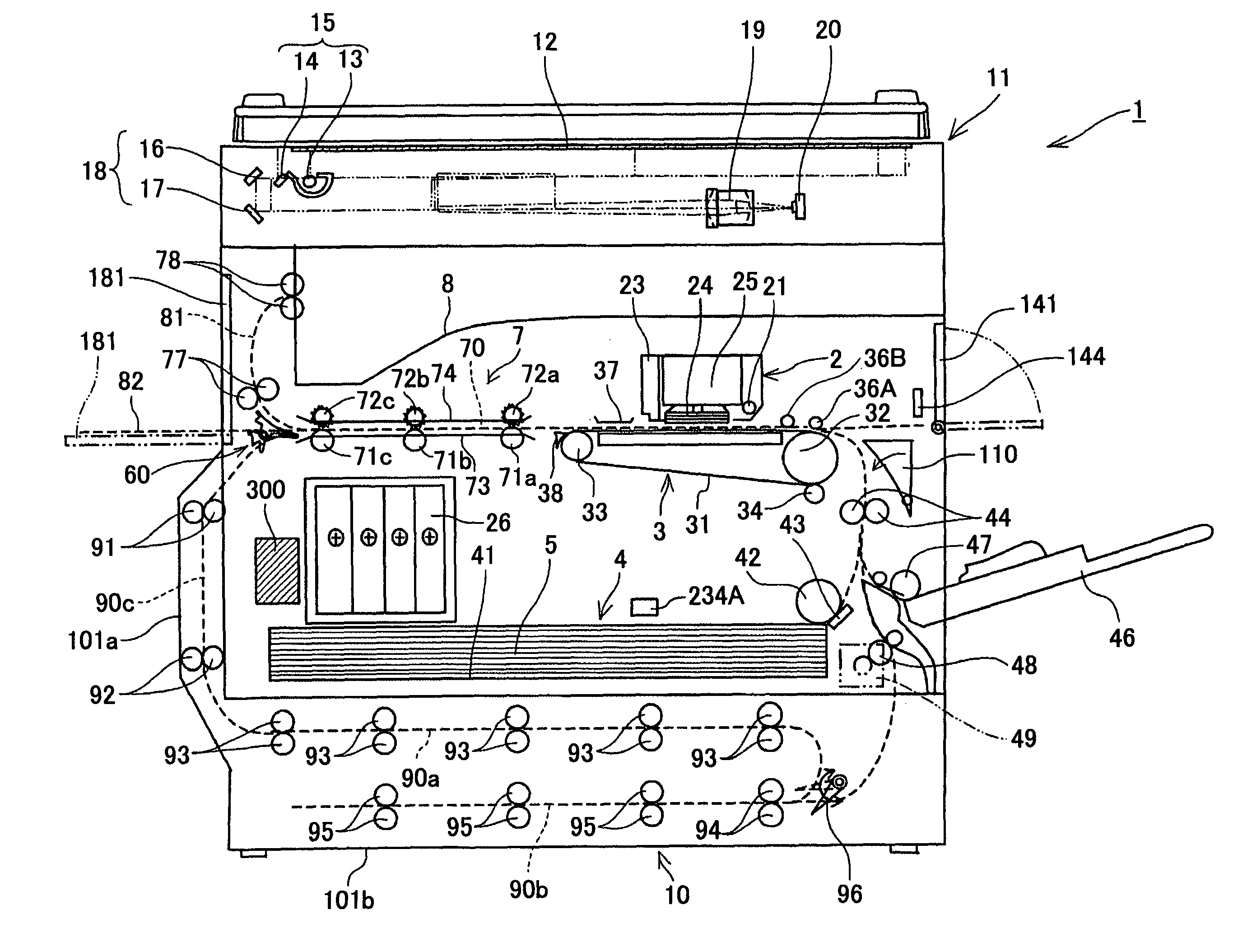
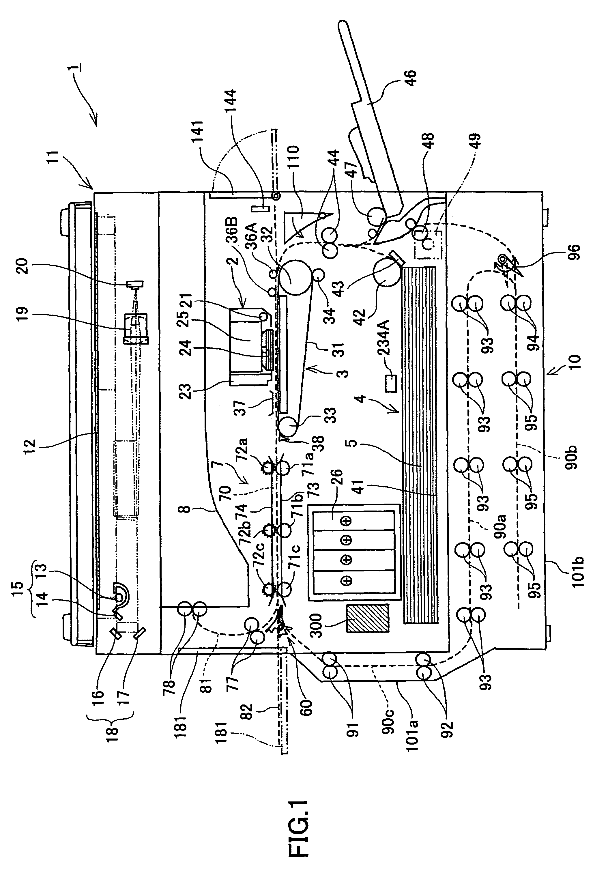
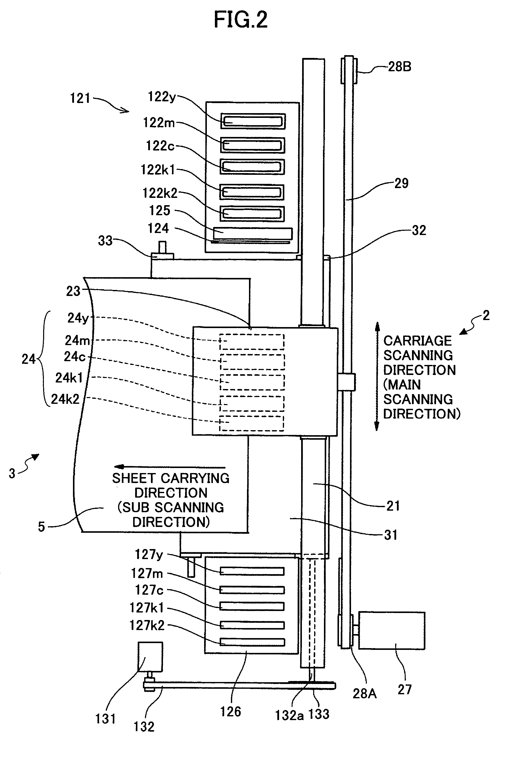
The patent text describes an image forming apparatus that prevents degradation of an image on a sheet and occurrence of jamming when both sides printing is executed. The apparatus stops the transportation of the sheet to the image forming unit after the image is formed on the first side of the sheet and before the image is formed on the second side of the sheet, until at least the tip of the second side of the sheet is not apart from the transport belt. The stopping necessity and time of the sheet can be determined based on information of the image, such as printing area, density, proportions among different size ink droplets, distribution, printing rate, and weighted printing rate. The number of ink droplets ejected on the first side of the sheet can also be used to determine the stopping necessity and time of the sheet. The type of sheet, temperature, and humidity can also be considered. A first pushing roller and a second pushing roller can be used to stop the sheet.

Problems solved by technology

When the cockling is large, the sheet may contact the nozzle surface so that the nozzle surface is stained and the sheet is also stained.
However, as described above, in a case where a sheet is transported by a transport belt to which an electric charge is applied by being attached thereto, when a part of the tip of the sheet is curled, since the part of the tip of the sheet does not contact the transport belt closely, the electrostatic force between the part of the tip of the sheet and the transport belt becomes small.
Consequently, the image on the sheet may be degraded and jamming may occur.

Method used


Image

  • Image forming apparatus
  • Image forming apparatus
  • Image forming apparatus

Examples


second embodiment

[0107]In the present invention, an printing area (ink droplet adhering area) on the total area of the first side of the sheet 5 is calculated and it is determined whether the sheet 5 is stopped being transported based on the calculated printing area.

[0108]The processes are described in detail. When both sides printing is executed (YES in S21), image data of an image which is printed on the first side of the sheet 5 are transferred to the printing controller 312 (S22) and the image is printed on the first side of the sheet 5 (S23). Then, an printing area (ink droplet adhering area) on the total area of the first side of the sheet 5 is calculated based on the image data of the image which is printed on the first side of the sheet 5 (S24). Then, it is determined whether the sheet 5 on whose first side the image is printed must be stopped being transported based on the calculated printing area (S25). That is, stopping necessity is determined. When it is determined that the sheet 5 must ...

third embodiment

[0113]In the present invention, image density on the total area of the first side of the sheet 5 is calculated and it is determined whether the sheet 5 is stopped being transported based on the calculated image density.

[0114]The processes are described in detail. When both sides printing is executed (YES in S31), image data of an image which is printed on the first side of the sheet 5 are transferred to the printing controller 312 (S32) and the image is printed on the first side of the sheet 5 (S33). Then, image density on the total area of the first side of the sheet 5 is calculated based on the image data of the image which is printed on the first side of the sheet 5 (S34). Then, it is determined whether the sheet 5 on whose first side the image is printed must be stopped being transported based on the calculated image density (S35). That is, stopping necessity is determined. When it is determined that the sheet 5 must be stopped after the image is printed on the first side of the...

fourth embodiment

[0118]In the present invention, proportions among different size ink droplets which are used for printing an image on the first side of the sheet 5 are calculated and it is determined whether the sheet 5 is stopped being transported based on the calculated proportions.

[0119]The processes are described in detail. When both sides printing is executed (YES in S41), image data of an image which is printed on the first side of the sheet 5 are transferred to the printing controller 312 (S42) and the image is printed on the first side of the sheet 5 (S43). Then, proportions among different size ink droplets which are used for printing the image on the first side of the sheet 5 are calculated based on the image data of the image which is printed on the first side of the sheet 5 (S44). Then, it is determined whether the sheet 5 on whose first side the image is printed must be stopped being transported based on the calculated proportions (S45). That is, stopping necessity is determined. When ...


PUM


Abstract

An image forming apparatus includes a transport belt rotating around rollers that transports a sheet by attaching the sheet thereto by an electrostatic force, an image forming unit which forms an image on the sheet transported by the transport belt by ejecting ink droplets from a recording head onto the sheet, and an duplex print unit which reverses the sheet, the first side of which has been printed, so as to form an image on the second side of the sheet. The apparatus stops the transportation of the sheet to the image forming unit after the image is formed on the first side of the sheet and before the image is formed on the second side of the sheet until at least the tip of the second side of the sheet is not apart from the transport belt.

Description

BACKGROUND[0001]1. Technical Field[0002]This disclosure generally relates to an image forming apparatus that can execute both sides printing on a sheet which is transported by a transport belt by an electrostatic force.[0003]2. Description of the Related Art[0004]As an image forming apparatus such as a printer, a facsimile, a copying apparatus, and a multifunctional apparatus that has the above functions, for example, an inkjet recording apparatus is widely known. In the inkjet recording apparatus, a recording head (an image forming unit) composed of ink droplet ejecting heads which eject ink droplets of recording liquid is used, and an image is formed on a recording medium (sheet) by ejecting the ink droplets of the recording liquid onto the recording medium from the recording head while carrying the recording medium. In this, the recording medium is not limited to a sheet, and any other recording medium such as an image transferring medium can be used as the recording medium; and ...

Claims


Application Information

Patent Timeline
Patent Type & Authority Patents(United States)
IPC IPC(8): B41J29/38B41J2/01B41J3/407
CPCB41J3/60B41J11/007
Inventor KAWABATA, KENICHI
Owner RICOH KK
Learn More