
Conceptual configuration modeling for application program integration

a technology of concept configuration and application program, applied in the field of data processing system, can solve the problems of the complexity of each application program itself, and the inability to assume the same user interface of products from the same vendor or supplier

Inactive Publication Date: 2010-08-10
LINKEDIN
View PDF19 Cites 6 Cited by
  • Summary
  • Abstract
  • Description
  • Claims
  • Application Information

AI Technical Summary

Benefits of technology

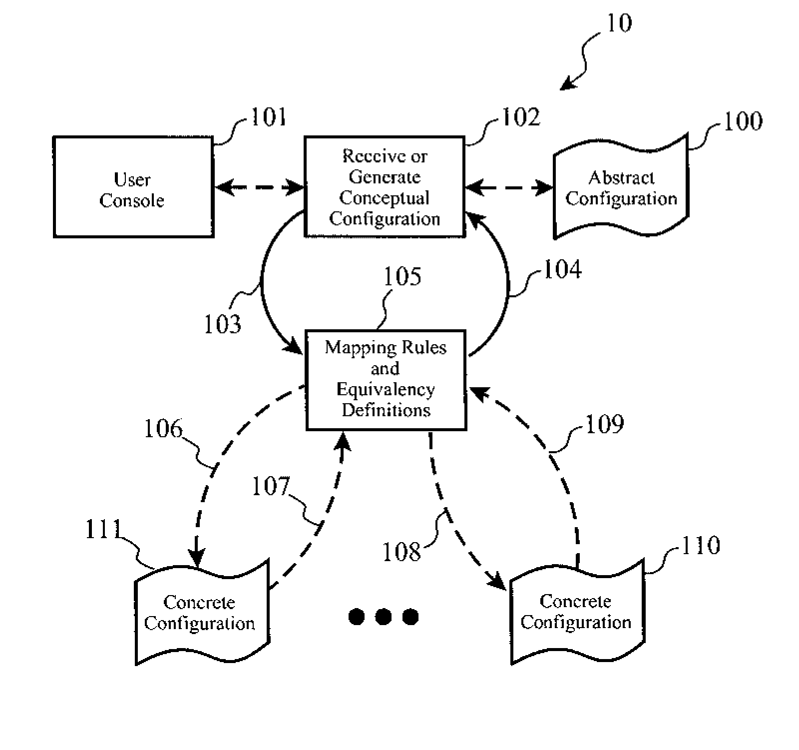
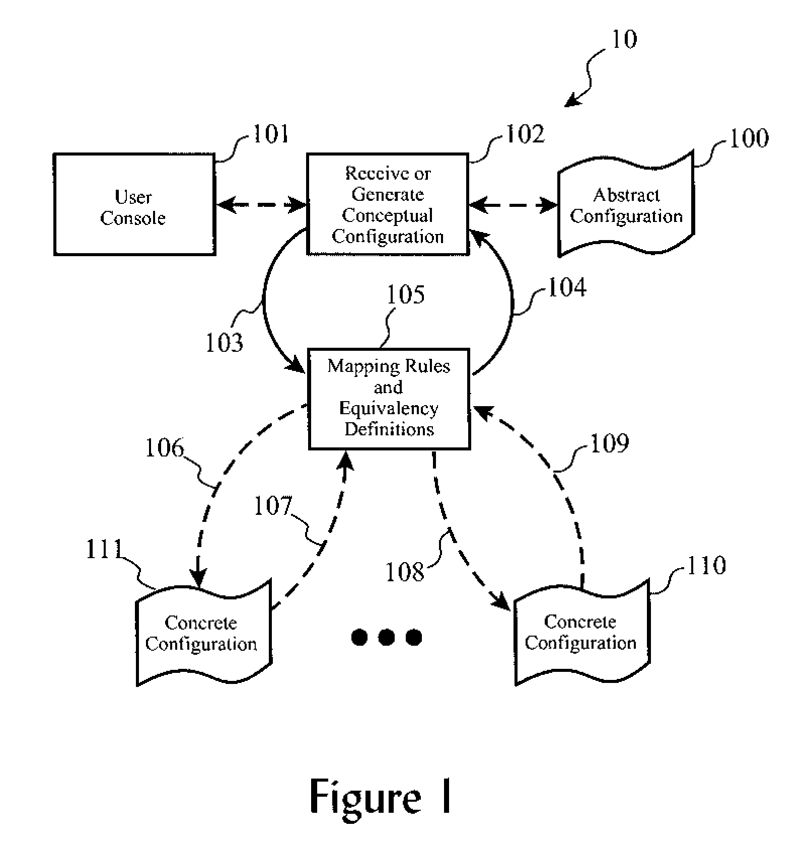
This approach enables efficient end-to-end integration of multiple application programs with reduced administrator expertise, lowering resource costs and simplifying the configuration process by using a unified abstract model to map and translate configuration elements across disparate applications.

Problems solved by technology

Each of these application programs themselves can be quite complex.
Even products from the same vendor or supplier cannot be assumed to use similar user interface (“UI”) concepts, configuration schemes and terminology because often times the products were originally developed for different market segments thereby driving differences, the products were acquired through corporate merger or product licensing, etc.
Thus, it cannot be assumed that an expert on a certain brand and model of database would naturally be familiar and efficient with using another database or with using another non-database program from the same vendor (e.g. same brand).
However, with the exception of the rare cases where related products are designed and developed in conjunction with the intent of integrated use cases, this integration can be a costly and daunting task.

Method used


Image

  • Conceptual configuration modeling for application program integration
  • Conceptual configuration modeling for application program integration
  • Conceptual configuration modeling for application program integration

Examples


based embodiments

Service-Based Embodiments

[0094]Alternative embodiments of the present invention include some or all of the foregoing logical processes and functions of the multi-layer configuration model invention being provided by configuring software, deploying software, downloading software, distributing software, or remotely serving clients in an on demand environment.

[0095]Software Deployment Embodiment. According to one embodiment of the invention, the methods and processes of the invention are distributed or deployed as a service by a service provider to a client's computing system(s). This enables a user to receive the benefits of the configuration model invention via a channel of having the software installed remotely, for example, over a network. Such an embodiment also may lend itself to remote configuration of application programs, such as an administrator being able to remotely configure a wide variety of application programs through an abstract configuration interface as described in ...


PUM


Abstract

First and second applications having disparate concrete configuration models are integrated into a unified abstract model wherein configuration elements and associated element values are used to control configurable functions of the first and second application programs, respectively, and wherein the second configuration element has a similar configuration function as the first configuration element; using a first equivalence definition reflecting a functional relationship between the first application configuration element and an abstract model configuration element having the similar configuration function, wherein the abstract model configuration is application-independent and platform-independent; using a second equivalence definition reflecting a functional relationship between the second application program configuration element and the abstract model configuration element; and producing and associating a second configuration element value with the second application configuration element wherein the second application program is automatically configured according to the second concrete application configuration model.

Description

CROSS-REFERENCE TO RELATED APPLICATIONS (CLAIMING BENEFIT UNDER 35 U.S.C. 120)[0001]NoneFEDERALLY SPONSORED RESEARCH AND DEVELOPMENT STATEMENT[0002]This invention was not developed in conjunction with any Federally sponsored contract.MICROFICHE APPENDIX[0003]Not applicable.INCORPORATION BY REFERENCE[0004]U.S. patent application Ser. No. 11 / 340,446, filed Jan. 26, 2006, by Chris Aniszczyk, et al., is hereby incorporation by reference in its entirety.BACKGROUND OF THE INVENTION[0005]1. Field of the Invention[0006]The present invention relates generally to an improved data processing system, and in particular, to a method for reducing implementation time for product-level integration of related computer program products to yield end-to-end solutions.[0007]2. Background of the Invention[0008]As computer systems become increasingly complex, solutions rely more and more on multiple application programs being integrated to each other to achieve a complete functionality needed by a user or ...

Claims


Application Information

Patent Timeline
Patent Type & Authority Patents(United States)
IPC IPC(8): G06F17/00
CPCG06F8/61G06F8/65G06F9/44505
Inventor ANISZCZYK, CHRISSAFABAKHSH, BORNAPADOVANI, PIERRE F.
Owner LINKEDIN
Learn More