
Wireless battery monitor

a battery monitor and wireless technology, applied in the field of storage batteries, can solve the problems of cumbersome prior art techniques and difficult implementation

Inactive Publication Date: 2010-08-10
FRANKLIN GRID SOLUTIONS LLC
View PDF607 Cites 104 Cited by
  • Summary
  • Abstract
  • Description
  • Claims
  • Application Information

AI Technical Summary

Benefits of technology

"The patent describes a device and method for testing the health of a battery using an electronic test. The test results are then transmitted wirelessly. The technical effect is that this allows for quick and easy testing of batteries without the need for a physical connection."

Problems solved by technology

These prior art techniques are cumbersome and are difficult to implement.

Method used


Image

  • Wireless battery monitor
  • Wireless battery monitor
  • Wireless battery monitor

Examples


Embodiment Construction

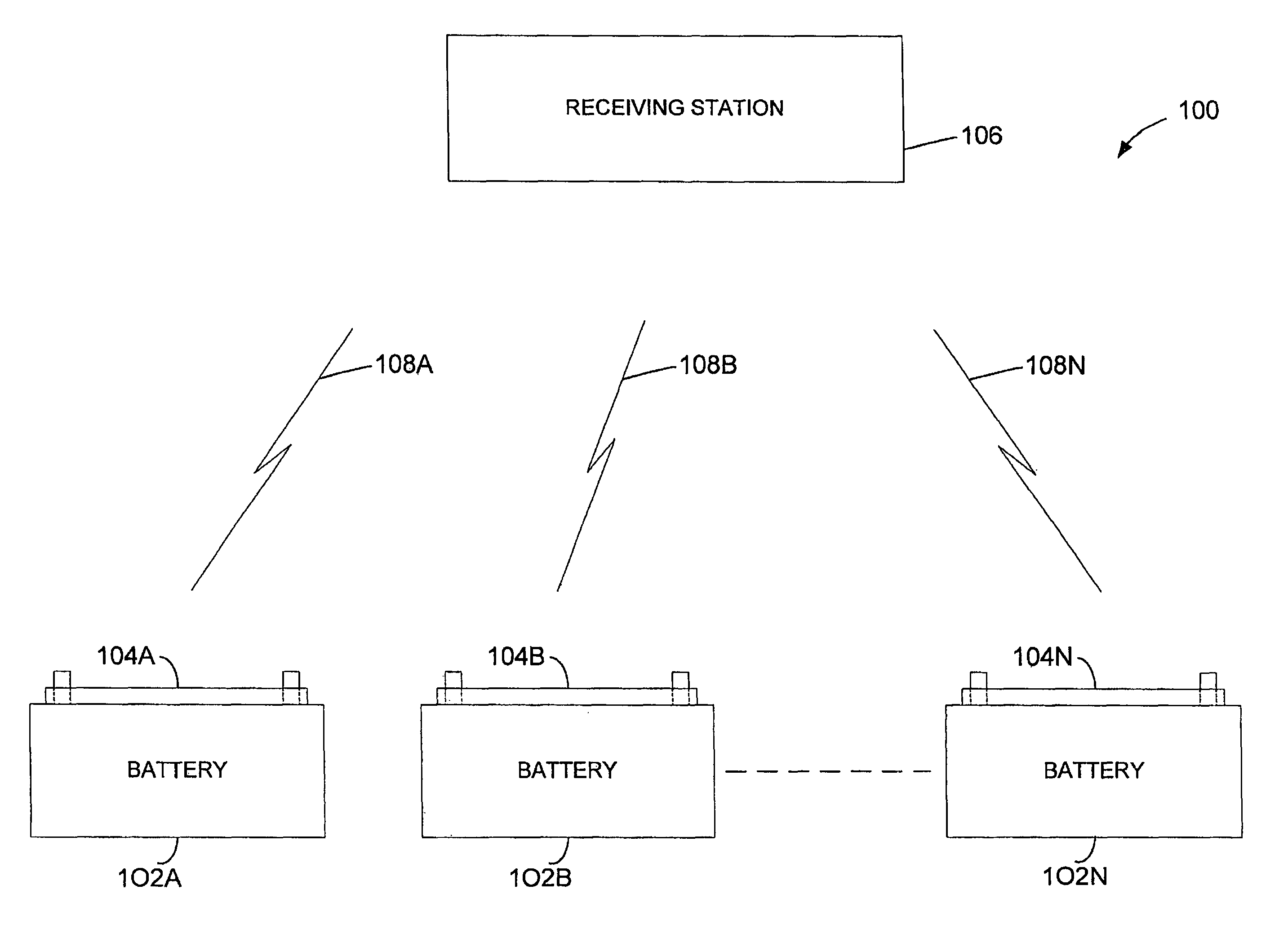
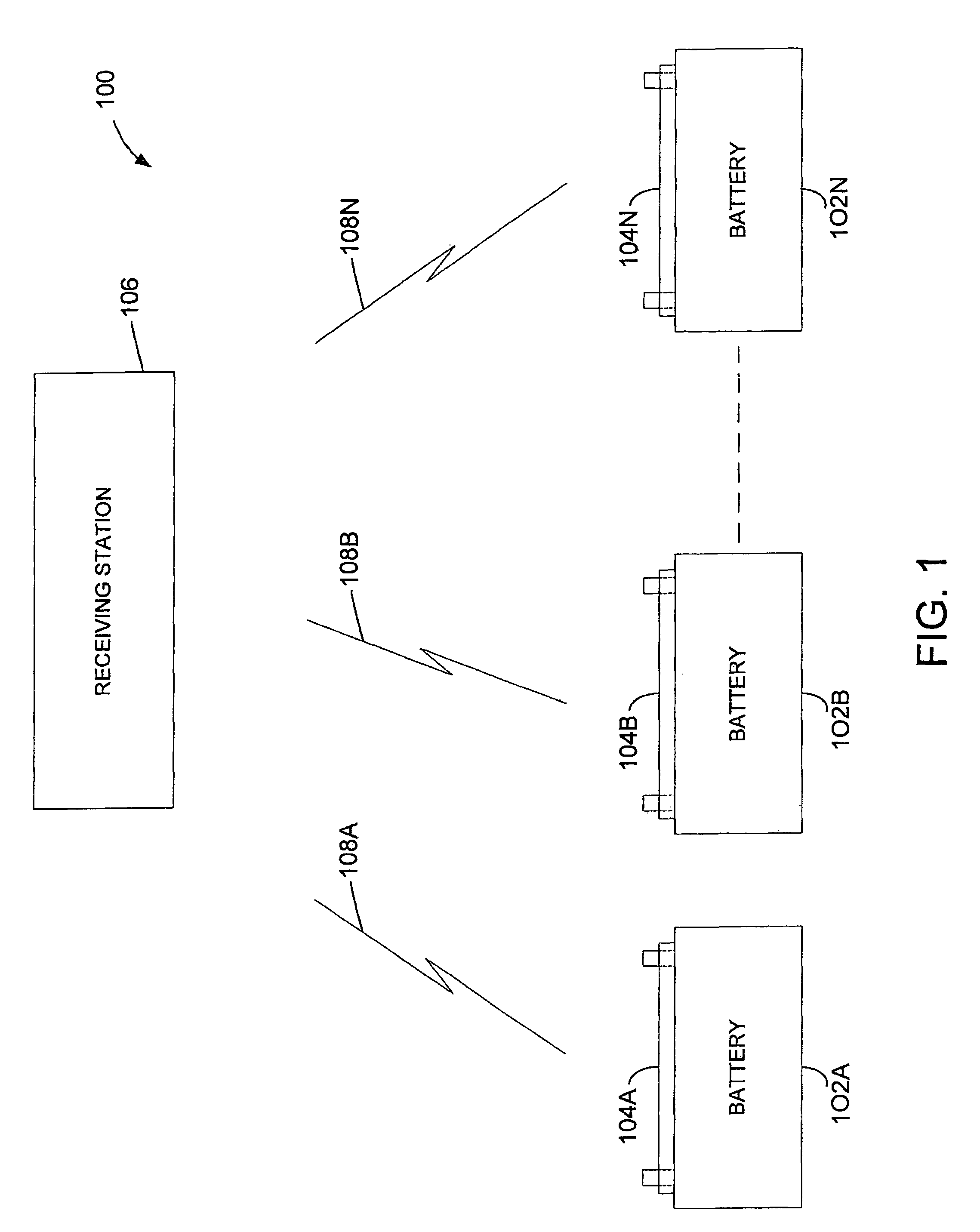
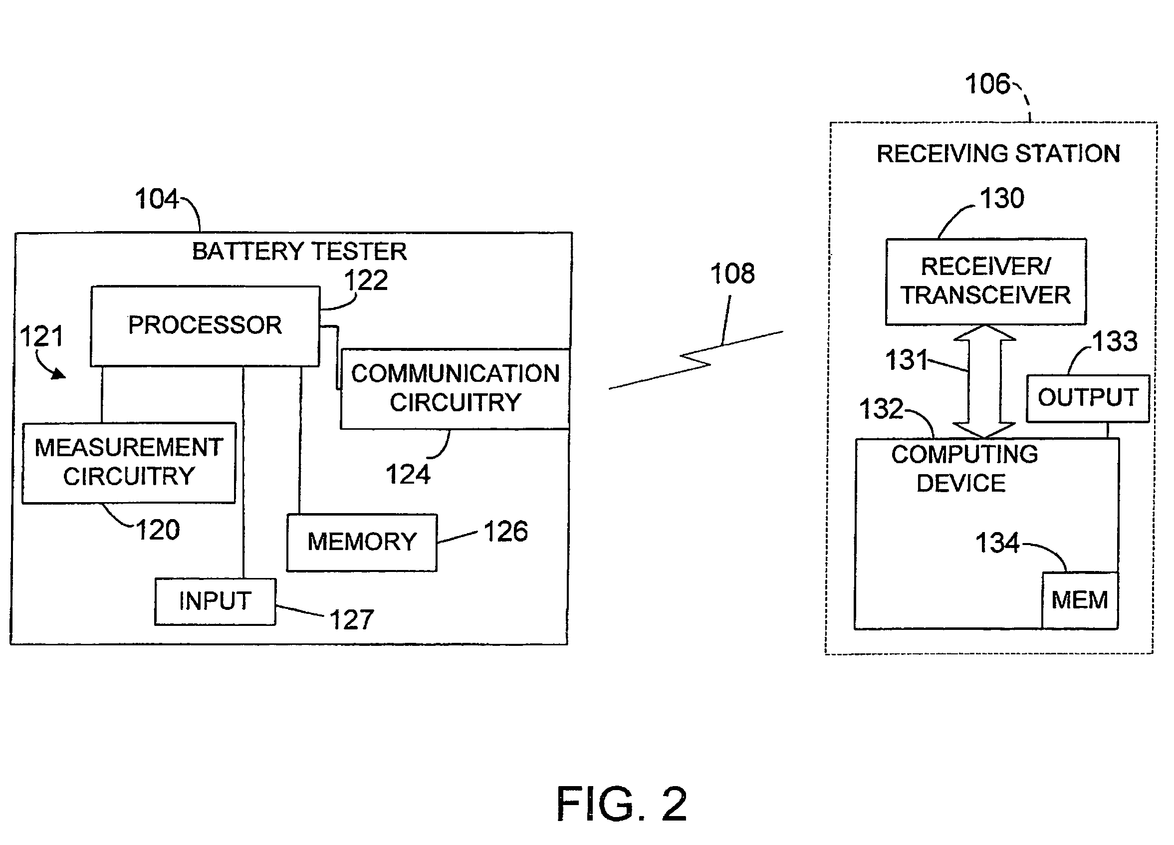
[0015]In the embodiments described below, an electronic battery tester provides battery test data, over a wireless communication medium, to a receiving station. Thus, when employed in a battery installation, the present invention reduces the large amount of wiring required for coupling individual cells and battery packs together to a controller. A battery installation that utilizes an embodiment of the present invention is described below in connection with FIG. 1. More detailed embodiments and method embodiments of the present invention are described further below in connection with FIGS. 2 through 8.

[0016]FIG. 1 is a simplified block diagram of a battery installation 100 including a plurality of batteries 102A, 102B . . . 102N. Each battery 102A . . . 102N is electrically coupled to a respective battery tester 104A, 104B . . . 104N. Each battery tester communicates with a data receiving station 106 over a wireless communication medium 108A, 108B . . . 108N, respectively. Receiving...


PUM


Abstract

An electronic battery tester and method includes generating battery test data from an electronic battery test. The battery test data is transmitted over a wireless communication medium. In another aspect, a method and apparatus is provided for receiving battery test data from a wireless communication medium.

Description

CROSS REFERENCE TO RELATED APPLICATIONS[0001]The present application claims the benefit of U.S. provisional patent application Ser. No. 60 / 548,513, filed Feb. 27, 2004 and U.S. provisional patent application Ser. No. 60 / 587,232, filed Jul. 12, 2004 and is a Continuation-In-Part of U.S. Ser. No. 10 / 914,304, filed Aug. 9, 2004, which is a Divisional of U.S. Ser. No. 10 / 093,853, filed Mar. 7, 2002 which is a Continuation-In-Part of and claims priority of U.S. Ser. No. 10 / 046,659, filed Oct. 29, 2001, which is a Divisional of Ser. No. 09 / 564,740, filed May 4, 2000, now U.S. Pat. No. 6,331,762, which is a Continuation-In-Part of application Ser. No. 08 / 962,754, filed Nov. 3, 1997, now U.S. Pat. No. 6,081,098 and also a Continuation-In-Part of application Ser. No. 09 / 575,627, filed May 22, 2000, which is a Continuation-In-Part of application Ser. No. 08 / 962,754, filed Nov. 3, 1997, now U.S. Pat. No. 6,081,098 and also claims priority to Provisional Application Ser. No. 60 / 132,622, filed M...

Claims


Application Information

Patent Timeline
Patent Type & Authority Patents(United States)
IPC IPC(8): G01R31/36G01R31/00H02J7/00H02J7/16
CPCG01R31/3627G01R31/3648H02J7/0004H02J7/0008H02J7/008H02J7/163G01R31/007G01R31/3689G01R31/385G01R31/371H02J7/00041H02J7/00036H02J7/00047
Inventor BERTNESS, KEVIN I.
Owner FRANKLIN GRID SOLUTIONS LLC
Learn More