
Superconducting articles having dual sided structures

a superconducting and article technology, applied in the direction of superconducting magnets/coils, superconductor devices, magnetic bodies, etc., can solve the problems of numerous engineering and manufacturing challenges, tapes do not represent commercially feasible products, and continue to exist. to achieve the effect of preventing burnou

Active Publication Date: 2010-08-10
SUPERPOWER INC
View PDF21 Cites 32 Cited by
  • Summary
  • Abstract
  • Description
  • Claims
  • Application Information

AI Technical Summary

Benefits of technology

The solution enables the production of long, cost-effective superconducting tapes that maintain critical current capacity even under overloading conditions, reducing material costs and improving the performance and commercial viability of high-temperature superconductor power components.

Problems solved by technology

However, it was not until somewhat recently that oxide-based high-temperature (high-Tc) superconductors have been discovered.
In this regard, it is estimated that the native resistance of copper-based commercial power components is responsible for quite significant losses in electricity, and accordingly, the power industry stands to gain significant efficiencies based upon utilization of high-temperature superconductors in power components such as transmission and distribution power cables, generators, transformers, and fault current interrupters.
While such potential benefits of high-temperature superconductors remain quite compelling, numerous technical challenges continue to exist in the production and commercialization of high-temperature superconductors on a large scale.
Among the many challenges associated with the commercialization of high-temperature superconductors, many exist around the fabrication of a superconducting tape that can be utilized for formation of various power components.
Although such conductors may be made in extended lengths needed for implementation into the power industry (such as on the order of kilometers), due to materials and manufacturing costs, such tapes do not represent a commercially feasible product.
However, to date, numerous engineering and manufacturing challenges remain prior to full commercialization of such second generation-tapes.

Method used


Image

  • Superconducting articles having dual sided structures
  • Superconducting articles having dual sided structures
  • Superconducting articles having dual sided structures

Examples


Embodiment Construction

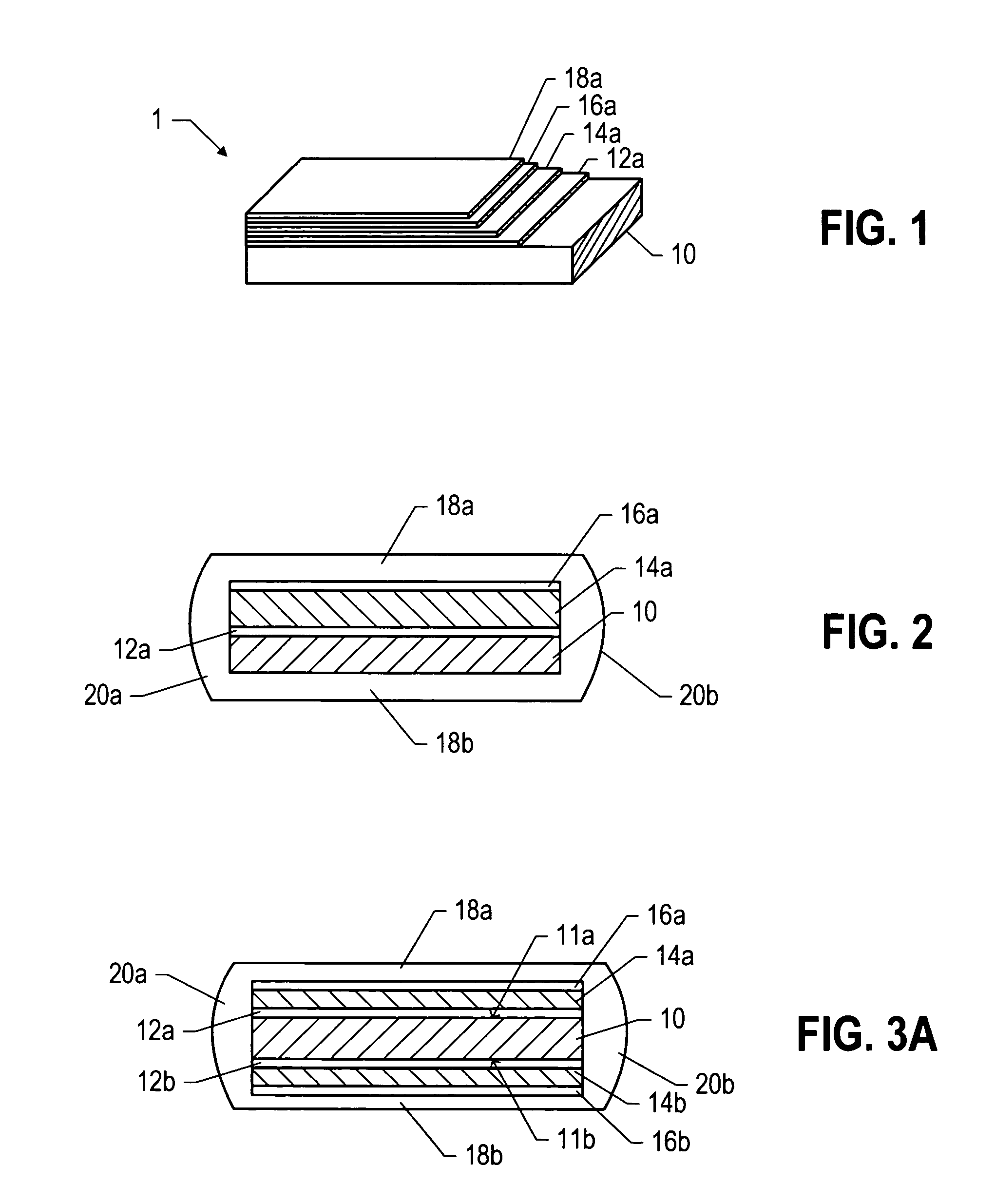
[0024]Turning to FIG. 1, the general layered structure of an HTS conductor according to an embodiment of the present invention is depicted. The HTS conductor includes a substrate 10, a buffer layer 12a overlying the substrate 10, an HTS layer 14a, followed by a capping layer 16a, typically a noble metal layer, and a stabilizer layer 18a, typically a non-noble metal.

[0025]The substrate 10 is generally metal-based, and typically, an alloy of at least two metallic elements. Particularly suitable substrate materials include nickel-based metal alloys such as the known Inconel® group of alloys. The Inconel® alloys tend to have desirable thermal, chemical and mechanical properties, including coefficient of expansion, thermal conductivity, Curie temperature, tensile strength, yield strength, and elongation. These metals are generally commercially available in the form of spooled tapes, particularly suitable for HTS tape fabrication, which typically will utilize reel-to-reel tape handling.

[0...


PUM


Abstract

A superconducting article includes a substrate; first and second buffer layers overlying the substrate, such that the substrate is positioned so as to be interposed between the first and second buffer layers, first and second superconductor layers overlying the first and second buffer layers. Further, the first and second stabilizer layers respectively overlying the first and second superconductor layers, the first and second stabilizer layers adapted to conduct current and prevent burnout of the first and second superconductor layers when the first and second superconductor layers are in a non-superconductive state.

Description

CROSS-REFERENCE TO RELATED APPLICATION(S)[0001]The present application is a continuation-in-part of U.S. application Ser. No. 11 / 130,349, filed May 16, 2005, which is a divisional application of U.S. application Ser. No. 10 / 607,945, filed Jun. 27, 2003, to which priority is claimed hereunder and which applications are both incorporated herein by reference in their entirety.BACKGROUND[0002]1. Field of the Invention[0003]The present invention is generally directed to superconducting or superconductor components, and in particular, a novel superconducting tape, power components incorporating same, and methods for utilizing and manufacturing same.[0004]2. Description of the Related Art[0005]Superconductor materials have long been known and understood by the technical community. Low-temperature (low-Tc) superconductors exhibiting superconductive properties at temperatures requiring use of liquid helium (4.2K), have been known since about 1911. However, it was not until somewhat recently ...

Claims


Application Information

Patent Timeline
Patent Type & Authority Patents(United States)
IPC IPC(8): H01L39/14H10N60/20H10N60/80
CPCH01L39/143H01L39/247Y10S428/93Y10T428/31504Y10T428/31678H10N60/203H10N60/0716
Inventor LEE, HEE-GYOUNXIE, YI-YUAN
Owner SUPERPOWER INC
Learn More