
Method for controlling shift during shift of automatic transmission

a technology of automatic transmission and shift, which is applied in the direction of mechanical equipment, instruments, etc., can solve the problems of deteriorating shift feel and long time needed for completion of shift, and achieve the effects of increasing the control pressure of the first frictional element, and reducing the control pressure of the second frictional elemen

Inactive Publication Date: 2010-08-03
HYUNDAI MOTOR CO LTD
View PDF4 Cites 3 Cited by
  • Summary
  • Abstract
  • Description
  • Claims
  • Application Information

AI Technical Summary

Benefits of technology

The present invention provides a method for controlling a smooth shift in an automatic transmission by modifying the control pressures for frictional elements in an N to N-2 shift and an N-2 to N-3 shift. The method allows for the simultaneous completion of the N-2 to N-3 shift and the N-2 to N-1 shift, resulting in a smooth shift with no interruptions. The control pressures of the frictional elements are modified to ensure a smooth shift, and the method includes a pre-charge pressure, a stand-by pressure, and a target releasing pressure. Overall, the method improves the performance and smoothness of shifting in automatic transmissions.

Problems solved by technology

Therefore, a time needed for completion of a shift may be long and shift feel may be deteriorated.

Method used


Image

  • Method for controlling shift during shift of automatic transmission
  • Method for controlling shift during shift of automatic transmission
  • Method for controlling shift during shift of automatic transmission

Examples


Embodiment Construction

[0036]Reference will now be made in detail to various embodiments of the present invention, examples of which are illustrated in the accompanying drawings and described below. While the invention will be described in conjunction with exemplary embodiments, it will be understood that present description is not intended to limit the invention to those exemplary embodiments. On the contrary, the invention is intended to cover not only the exemplary embodiments, but also various alternatives, modifications, equivalents and other embodiments, which may be included within the spirit and scope of the invention as defined by the appended claims.

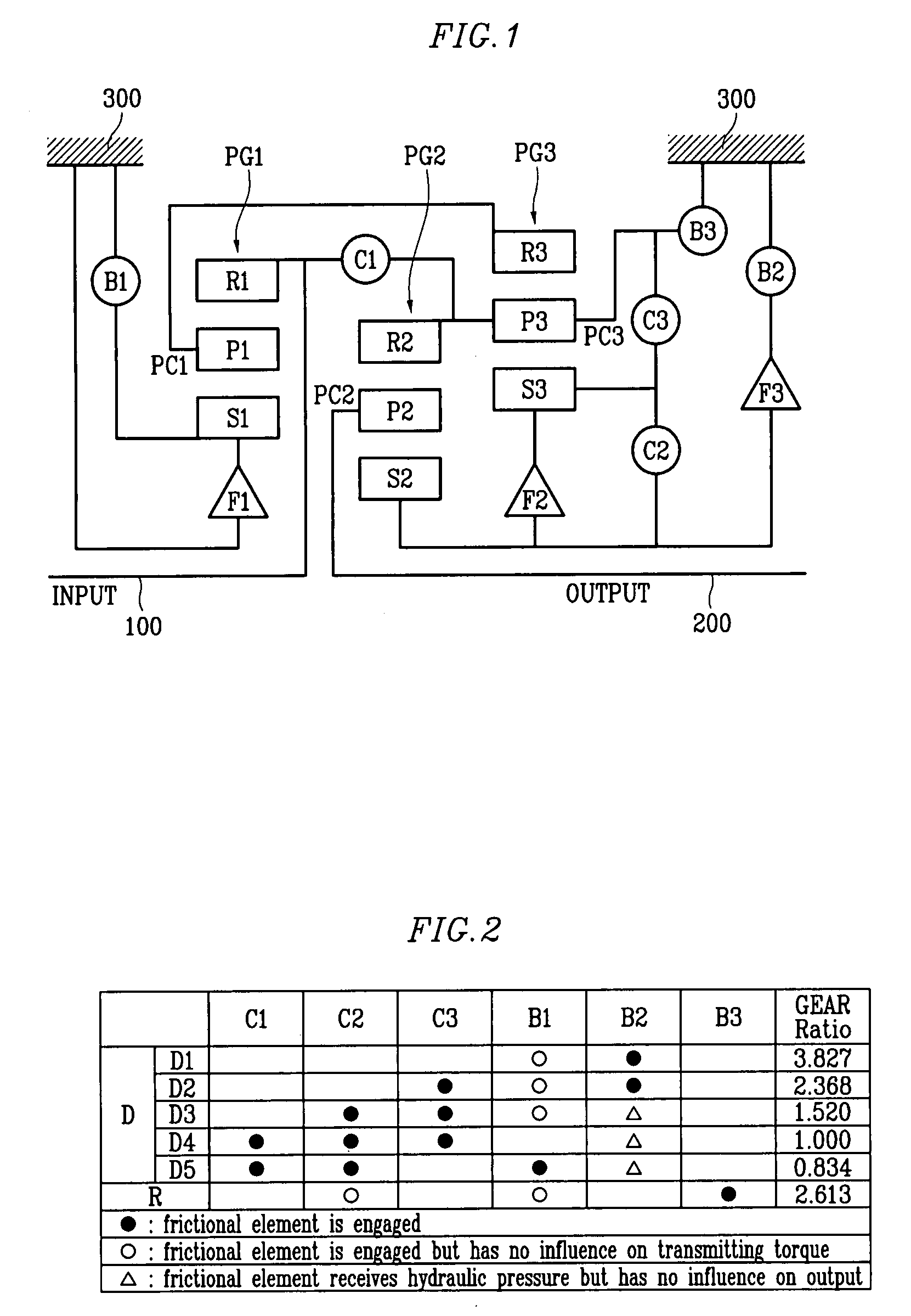
[0037]FIG. 1 is a schematic diagram showing a power train of an automatic transmission that is applicable to a method for controlling a shift during a shift according to an exemplary embodiment of the present invention.

[0038]As shown in FIG. 1, a power train of an automatic transmission that is applicable to a method for controlling a shift during a ...


PUM


Abstract

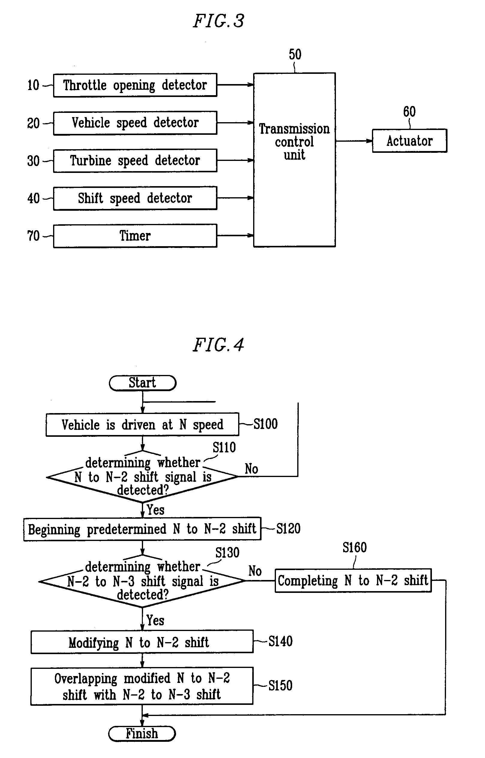
A method for controlling a shift during a shift of an automatic transmission controls to complete an N to N-2 shift and an N-2 to N-3 shift simultaneously such that the shift during a shift is smoothly performed when the N-2 to N-3 shift where one frictional element is released is required to be performed during the N to N-2 shift where another frictional element is released and the other frictional element is engaged. A method for controlling a shift during a shift of an automatic transmission may overlap an N to N-2 shift where a first frictional element is engaged and a second frictional element is released with an N-2 to N-3 shift where a third frictional element is released, wherein a release of the second frictional element begins after an engagement of the first frictional element begins, and a release of the third frictional element begins after an N-2 to N-3 shift signal is detected, wherein the engagement of the first frictional element and the release of the second and third frictional elements are simultaneously completed.

Description

CROSS-REFERENCE TO RELATED APPLICATION[0001]This application claims priority to and the benefit of Korean Patent Application No. 10-2006-0125186 filed in the Korean Intellectual Property Office on Dec. 9, 2006, the entire contents of which are incorporated herein by reference.BACKGROUND OF THE INVENTION[0002](a) Field of the Invention[0003]The present invention relates to a method for controlling a shift during a shift of an automatic transmission. More particularly, the present invention relates to a method for controlling a shift during a shift of an automatic transmission that controls to complete an N to N-2 shift and an N-2 to N-3 shift simultaneously such that the shift during a shift is smoothly performed when the N-2 to N-3 shift where one frictional element is released is required to be performed during the N to N-2 shift where another frictional element is released and a further frictional element is engaged.[0004](b) Description of the Related Art[0005]Generally, an autom...

Claims


Application Information

Patent Timeline
Patent Type & Authority Patents(United States)
IPC IPC(8): F16H31/00G06F19/00
CPCF16H61/061F16H61/686Y10T477/6936F16H2306/14Y10T477/6937F16H2061/0444F16H61/04F16H61/06
Inventor LEE, JIN SOO
Owner HYUNDAI MOTOR CO LTD
Learn More