Glued heald mounting rail

a mounting rail and glued technology, applied in the field of shaft rods, can solve the problems of unnecessary addition of connecting means such as rivets or screws, and achieve the effects of simple engineering design, improved anchoring of holding section, and simple manner

Inactive Publication Date: 2010-07-27
GROZ BECKERT KG
View PDF17 Cites 3 Cited by
  • Summary
  • Abstract
  • Description
  • Claims
  • Application Information

AI Technical Summary

Benefits of technology

[0010]These measures permit a particularly simple and reliable process for the manufacture of the shaft rod. The space-filling adhesive fills the accommodation space at least in so far as the holding section extends into said space. Preferably, the space-filling adhesive fills the larger portion of the accommodation space while the holding section fills the smaller portion of the accommodation space. In other words: the holding section extends with significant play into the accommodation space, so that said holding section can always be easily inserted into the accommodation space, irrespective of the manufacturing tolerances. To achieve this, the accommodation space has, in the region of its mouth, a width of cross-section—in opening direction, as well as in transverse direction of the mouth—that is greater than the material thickness of the holding section. The space-filling adhesive compensates for manufacturing tolerances and secures the holding section positively bonded in the accommodation space. This results in a cost-effective connection.
[0012]The holding section is preferable a part of the heald mounting rail, however, may also be part of the rod body. Preferably, it is configured as a foot displaying uniform material thickness. Preferably, the holding section is part of a bent sheet metal part which represents the heald mounting rail or also the rod body. In order to anchor the holding section in the accommodation space, said section—in connected state—is angled in an area located in the accommodation space. This improves anchoring of the holding section in the accommodation space.
[0013]The accommodation space is preferably provided on the rod body. To do so, the rod body may also be configured as an extrusion-molded aluminum profile. It may also comprise a bent sheet metal part or several components that are connected to each other by welding, gluing or other connecting techniques. The arrangement of the accommodation space on the rod body results in simple engineering designs of the heald mounting rail that can then be configured as a bent sheet metal part in a particularly simple manner. Preferably, the height / width ratio is <5. As a result of this, a compact, stiff mounting rail is produced. In addition to the at least one bent edge, the mounting rail may have additional bent edges, thus resulting in a stable, strong mounting rail. The bent edges are disposed to stiffen the sheet metal strip that constitutes the mounting rail.
[0015]Due to the pivoting or rotating movements of the rod body and the heald mounting rail toward each other, assembly of a long mounting rail of a shaft rod having a length of 4 to 6 meters, for example, is facilitated. The space-filling adhesive can be introduced in the accommodation space before joining the mounting rail and the rod body. After the mounting rail has been pivoted in, the adhesive flows around the holding section thus fixing said section in place. Depending on the composition of the adhesive, it is also possible to introduce it into the accommodation space following the assembly, i.e., after pivoting the mounting rail into the accommodation space of the rod body. A preferably thinly liquid adhesive then fills the accommodation space almost completely. After pivoting-in the mounting rail, preferably at least two surfaces of the connecting section that are at an angle relative to each other abut against the surfaces of the accommodation space, so that the heald mounting rail is fixed in the desired set position when the adhesive hardens. It is also possible to provide stop means on the connecting device, said means resulting in a stop effect and temporarily securing the heald mounting rail. This simplifies the fixation of the heald mounting rail while the adhesive is hardening.

Problems solved by technology

As a result of the shape of the regions that are in engagement with each other, additional connecting means such as, e.g., rivets or screws, become unnecessary.

Method used


Image

  • Glued heald mounting rail
  • Glued heald mounting rail
  • Glued heald mounting rail

Examples


Embodiment Construction

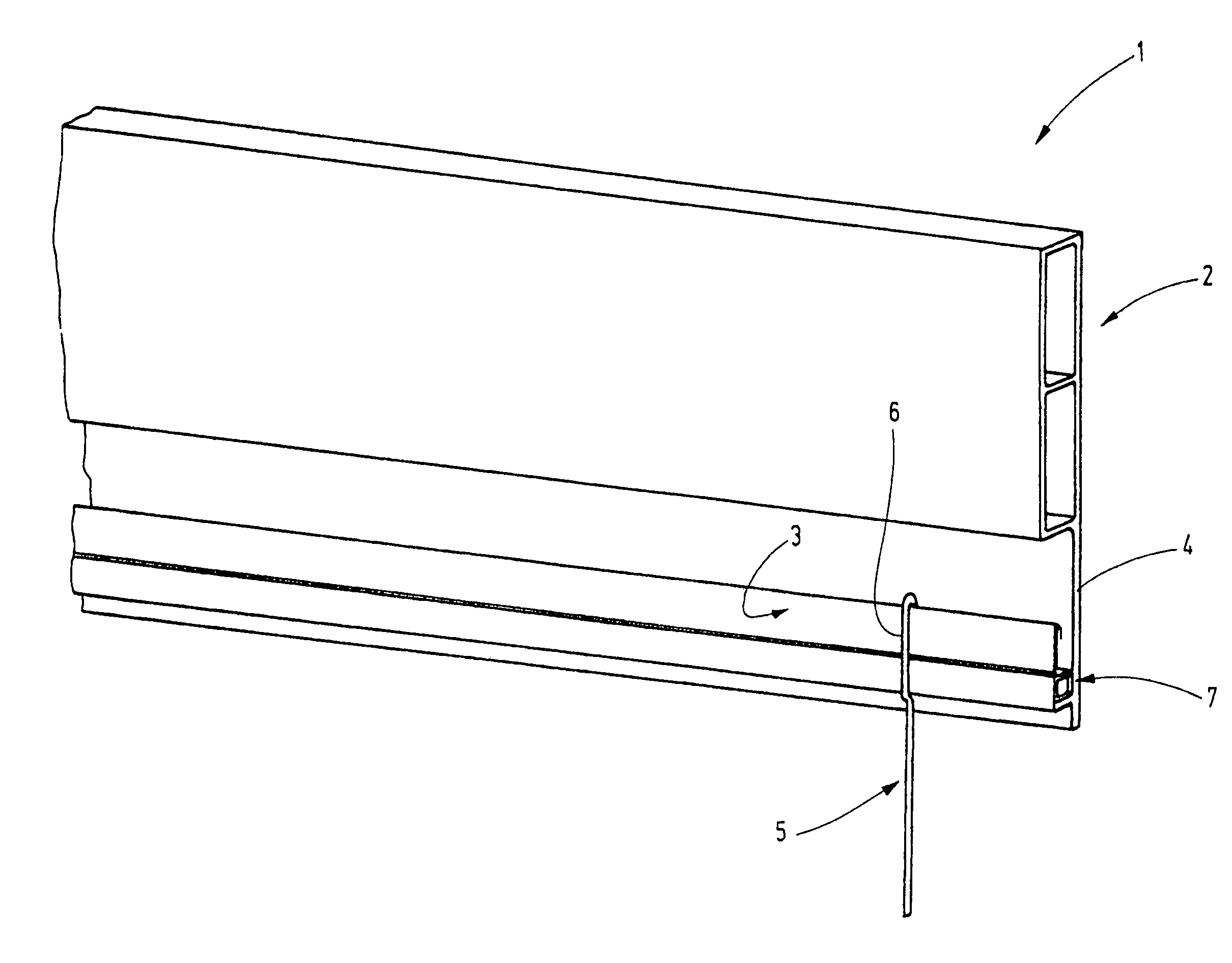
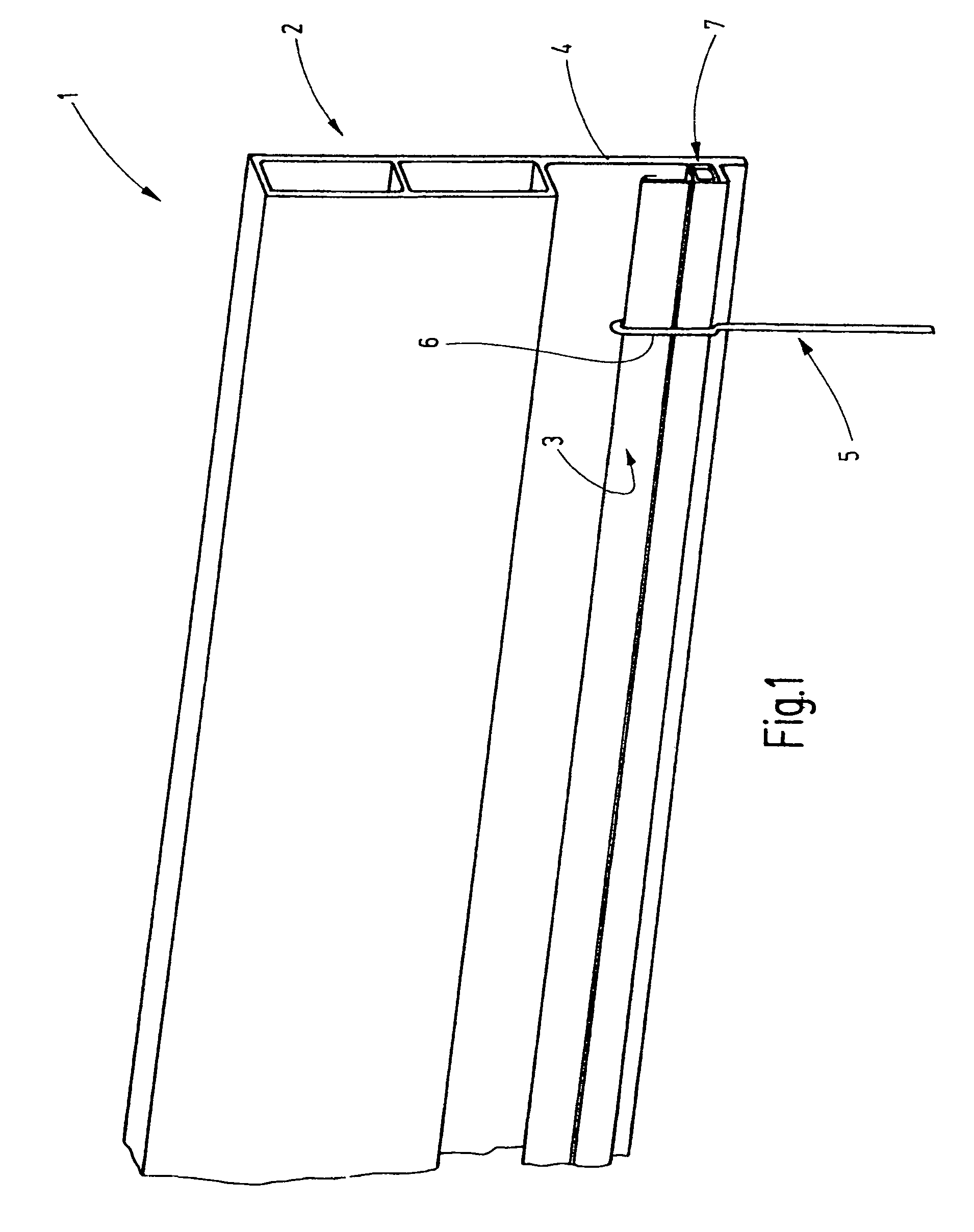
[0026]FIG. 1 shows a shaft rod 1 of a heald shaft. The shaft rod 1 comprises a rod body 2 and a heald mounting rail 3 that are connected to each other. The rod body 2 may extend over a length of several meters. It provides the necessary vertical stiffness of the shaft rod 1. Preferably, as shown, it consists of an extrusion-molded aluminum profile that has one or more chambers in the form of cavities. The rod body 2 has a strip section 4 that extends vertically away from the chamber profile and is supported on the heald mounting rail 3. However, alternatively, the rod body 2 may be a differently configured body. For example, it may be constructed of one or more parts that are connected to each other by appropriate connecting techniques such as gluing, welding and the like. Thus, said body may be assembled of sheet metal parts consisting of non-ferrous metals, of plastic parts and similar elements.

[0027]The heald mounting rail 3 is preferably a bent sheet metal part. It is used for t...


PUM


Abstract

A shaft rod (1) having a heald mounting rail (3) glued to the rod body (2) using a space-filling adhesive (19) provided in an accommodation space (14) on the mounting rail (3) or the rod body (2) and having a greater volume than a holding section (10) formed on the rod body (2) or the mounting rail (3). Preferably, the holding section (10) and the accommodation space (14) are configured such that the two parts can only be inserted into each other with a pivoting movement. To achieve this, the holding section (10) preferably has a part (21) extending transverse to the mouth (17) of the accommodation space (14), and being wider than the mouth (17), thus extending behind a wall section or part (31, 34) of the accommodation space (14). Preferably, the accommodation space (14) and the holding section (10) are configured as hook profiles that engage each other.

Description

CROSS REFERENCE TO RELATED APPLICATION[0001]The present application claims the priority of European Patent Application No. 07 017 730.8, filed Sep. 11, 2007, the subject matter of which, in its entirety, is incorporated herein by reference.BACKGROUND OF THE INVENTION[0002]The invention relates to a shaft rod for setting up a heald shaft for a weaving machine.[0003]Heald shafts in weaving machines are disposed to accommodate a large number of healds, whereby each heald has a thread eye in order to guide a warp thread. Additional warp threads run between the healds. As a result of the up-and-down movement of the heald shaft the warp threads guided by the healds can be moved out of the plane of the remaining healds, as a result of which a shed is created into which the weft thread can be carried.[0004]In most cases, each heald has at least two horizontal shaft rods that are parallel to each other and that have ends that are connected to each other by vertical lateral supports. Thus, th...

Claims


Application Information

Patent Timeline
Patent Type & Authority Patents(United States)
IPC IPC(8): D03C9/02D03C9/06D03C9/04D03C13/00
CPCD03C9/0633
Inventor DROPE, STEFANGESING, KARL-HEINZFEHRENBACHER, ECKHARD
Owner GROZ BECKERT KG
Why Eureka
Try Eureka