
Cutting balloon catheter with improved balloon configuration

a balloon catheter and balloon configuration technology, applied in balloon catheters, medical science, surgery, etc., can solve the problems of major problems such as blockage or narrowing of blood vessels, lack of oxygenation of the heart, and obstruction of the heart and vascular diseases, and achieve the effect of improving the folding and refolding abilities of the balloon

Inactive Publication Date: 2010-07-20
BOSTON SCI SCIMED INC
View PDF222 Cites 46 Cited by
  • Summary
  • Abstract
  • Description
  • Claims
  • Application Information

AI Technical Summary

Benefits of technology

[0006]The present invention relates to angioplasty balloon catheters. In at least some embodiments, an example balloon catheter may include a catheter shaft having a balloon coupled thereto. The balloon may include one or more cutting members or blades. Additionally, the balloo

Problems solved by technology

Heart and vascular disease are major problems in the United States and throughout the world.
Conditions such as atherosclerosis result in blood vessels becoming blocked or narrowed.
This blockage can result in lack of oxygenation of the heart, which has significant consequences since the heart muscle must be well oxygenated in order to maintain its blood pumping action.
One of the major obstacles in treating coronary artery disease and / or treating blocked blood vessels is re-stenosis.
It is believed typical angioplasty balloons, alone, may not be able to expand certain of these hardened lesions.
Another potential obstacle that may accompany treatments that include expansion of a stenosis with an angioplasty balloon is the removal of the balloon from the vessel.
This could subject healthy tissue to unnecessary contact with the cutting edge and resultant abrasion or cutting during the balloon removal procedure.

Method used


Image

  • Cutting balloon catheter with improved balloon configuration
  • Cutting balloon catheter with improved balloon configuration
  • Cutting balloon catheter with improved balloon configuration

Examples


Embodiment Construction

[0014]The following description should be read with reference to the drawings wherein like reference numerals indicate like elements throughout the several views. The detailed description and drawings illustrate example embodiments of the claimed invention.

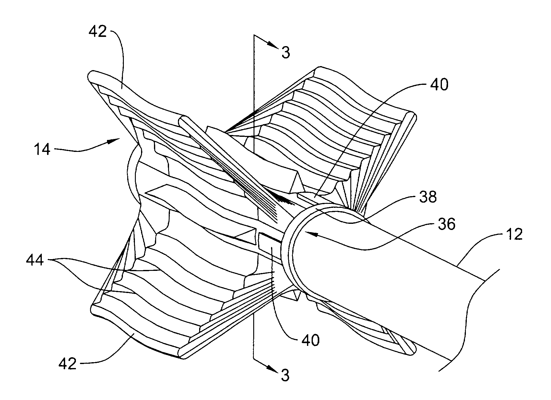
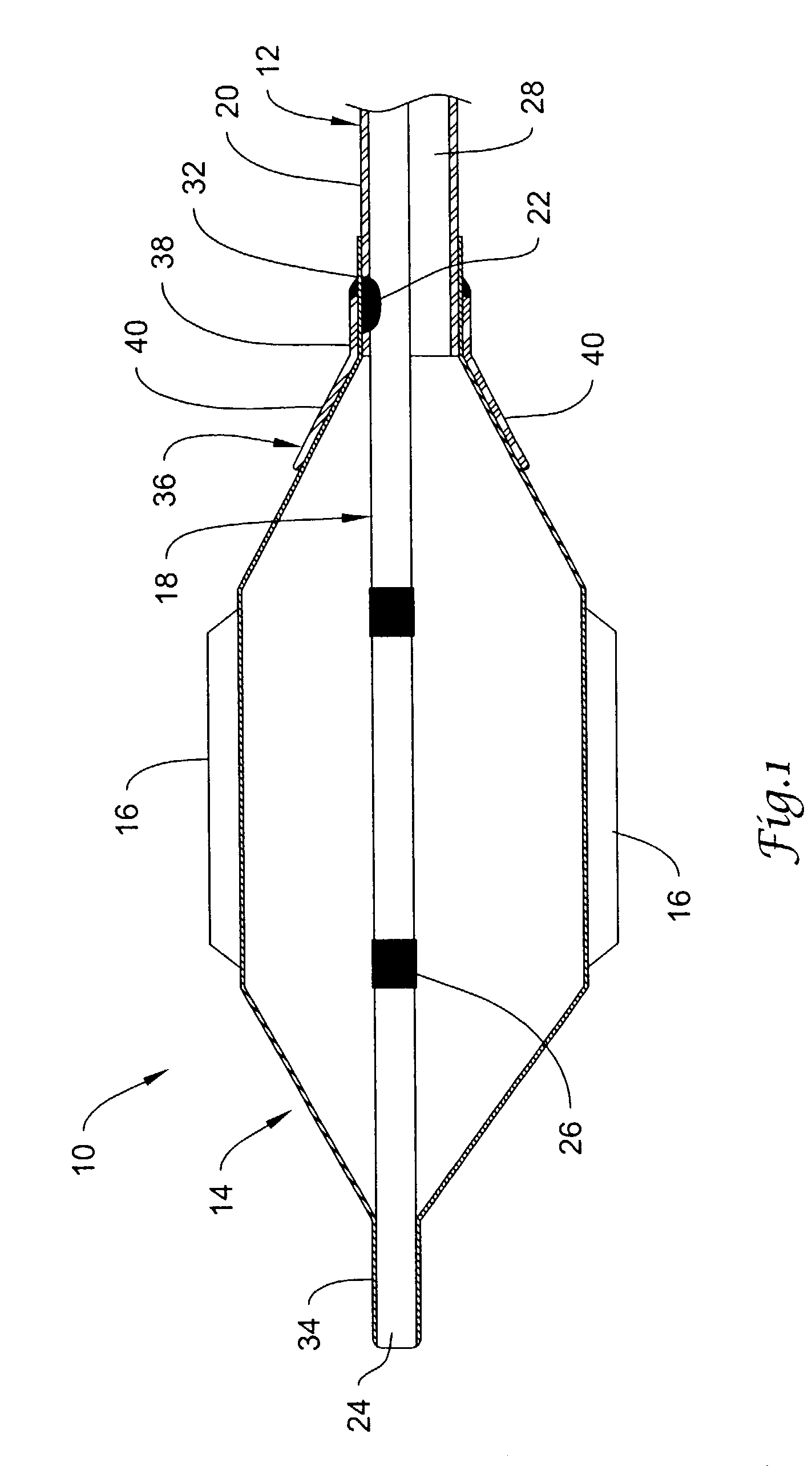
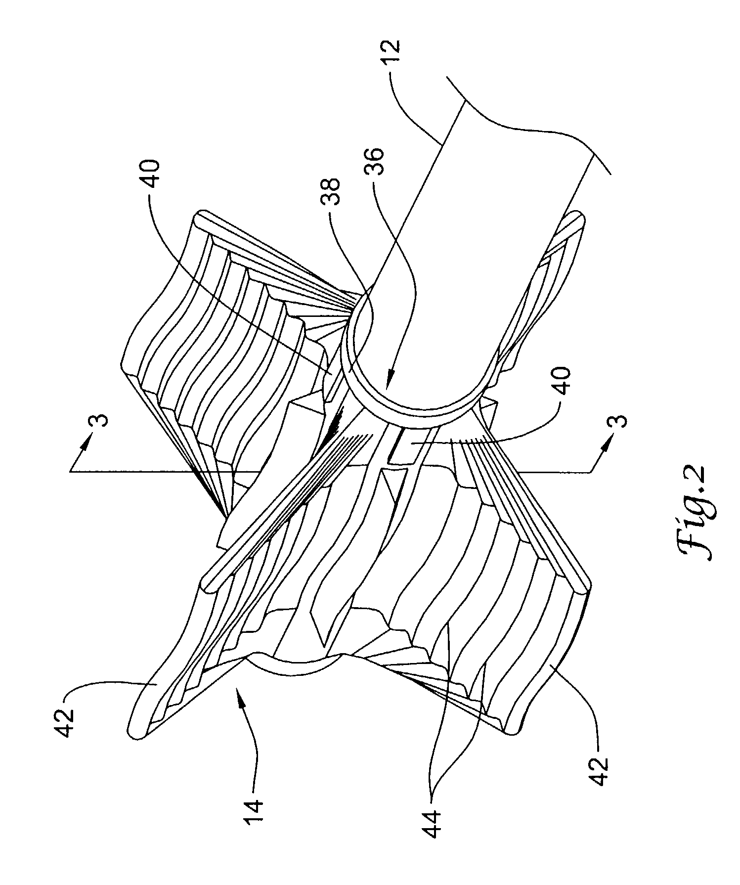
[0015]FIG. 1 is a partial cross-sectional side view of a distal portion of a catheter 10. Catheter 10 includes a catheter shaft 12 and an expandable balloon 14 coupled to shaft 12. Balloon 14 may include one or more cutting members 16 that may be used, for example, to sever tissue adjacent a stenosis and / or otherwise compliment the expansion of a stenotic lesion. In general, balloon catheter 10 may include similarities in structure and use to other balloon catheters. For example, catheter 10 can be advanced through the vasculature to a position adjacent a target area (e.g., an intravascular lesion) and balloon 14 may be expanded to expand the lesion. Uses for catheter 10 may include cardiac interventions as well as peripheral inte...


PUM


Abstract

An angioplasty balloon catheter and method of making and using the same. The balloon catheter may include a catheter shaft and a balloon coupled to the shaft. The balloon may include one or more cutting edges or member and may include one or more wings. The wings may include an undulating surface.

Description

FIELD OF THE INVENTION[0001]The present invention pertains to angioplasty and angioplasty balloon catheters. More particularly, the present invention pertains to angioplasty balloon catheters that include one or more cutting edges and angioplasty balloons with improved folding and re-folding properties.BACKGROUND[0002]Heart and vascular disease are major problems in the United States and throughout the world. Conditions such as atherosclerosis result in blood vessels becoming blocked or narrowed. This blockage can result in lack of oxygenation of the heart, which has significant consequences since the heart muscle must be well oxygenated in order to maintain its blood pumping action.[0003]Occluded, stenotic, or narrowed blood vessels may be treated with a number of relatively non-invasive medical procedures including percutaneous transluminal angioplasty (PTA), percutaneous transluminal coronary angioplasty (PTCA), and atherectomy. Angioplasty techniques typically involve the use of...

Claims


Application Information

Patent Timeline
IPC IPC(8): A61B17/22A61F2/958
CPCA61B17/320725A61B2017/22061A61M2025/1004A61M2025/1086
Inventor WU, SHOW-MEAN STEVEROMAN, RICARDO DAVIDCRUZ, REYNALDO
Owner BOSTON SCI SCIMED INC
Learn More