
Upper body exercise cycle

a technology for upper body exercise and cycle, which is applied in the direction of gymnastic exercise, frictional force resistor, sport apparatus, etc., can solve the problems of reducing the possibility of injury from a crank arm rotating faster than the user's capability, and achieves the effect of reducing the possibility of injury, facilitating proper foot positioning, and facilitating transportation

Active Publication Date: 2010-07-20
JOHNNY G METHOD
View PDF42 Cites 8 Cited by
  • Summary
  • Abstract
  • Description
  • Claims
  • Application Information

AI Technical Summary

Benefits of technology

"The present invention is an upper body exercise cycle that allows users to exercise both arms or focus on one arm. The device features a ratchet and pawl mechanism that allows the crank arms to be independent, making it easy to use. The flywheel employs an adjustable resistance mechanism to change the difficulty level for users of different strength. The flywheel also employs a ratchet and pawl mechanism to allow it to freewheel, reducing the possibility of injury. The headstock and seat may be adjusted to accommodate users of various sizes, and the adjustability of the headstock allows users to isolate different muscle groups. The upper body exercise cycle may be placed on a base plate ramp for proper feet positioning and transportation. The unique design of the cycle makes it easy to use and aesthetically pleasing. The use of the cycle provides cardiovascular and upper body strength benefits, and the natural, smooth, rhythmic rotational movements provide a comfortable way of exercising."

Problems solved by technology

In other words, although the crank arms can drive the flywheel, but the flywheel cannot drive the crank arms, thereby reducing the possibility of injury from a crank arm rotating faster than the user's capability.

Method used


Image

  • Upper body exercise cycle
  • Upper body exercise cycle
  • Upper body exercise cycle

Examples


Embodiment Construction

[0026]The detailed description set forth below in connection with the appended drawings is intended as a description of presently-preferred embodiments of the invention and is not intended to represent the only forms in which the present invention may be constructed or utilized. The description also sets forth the functions and the sequence of steps for operating the invention in connection with the illustrated embodiments. It is to be understood, however that the same or equivalent functions and sequences may be accomplished by different embodiments that are also intended to be encompassed within the spirit and scope of the invention.

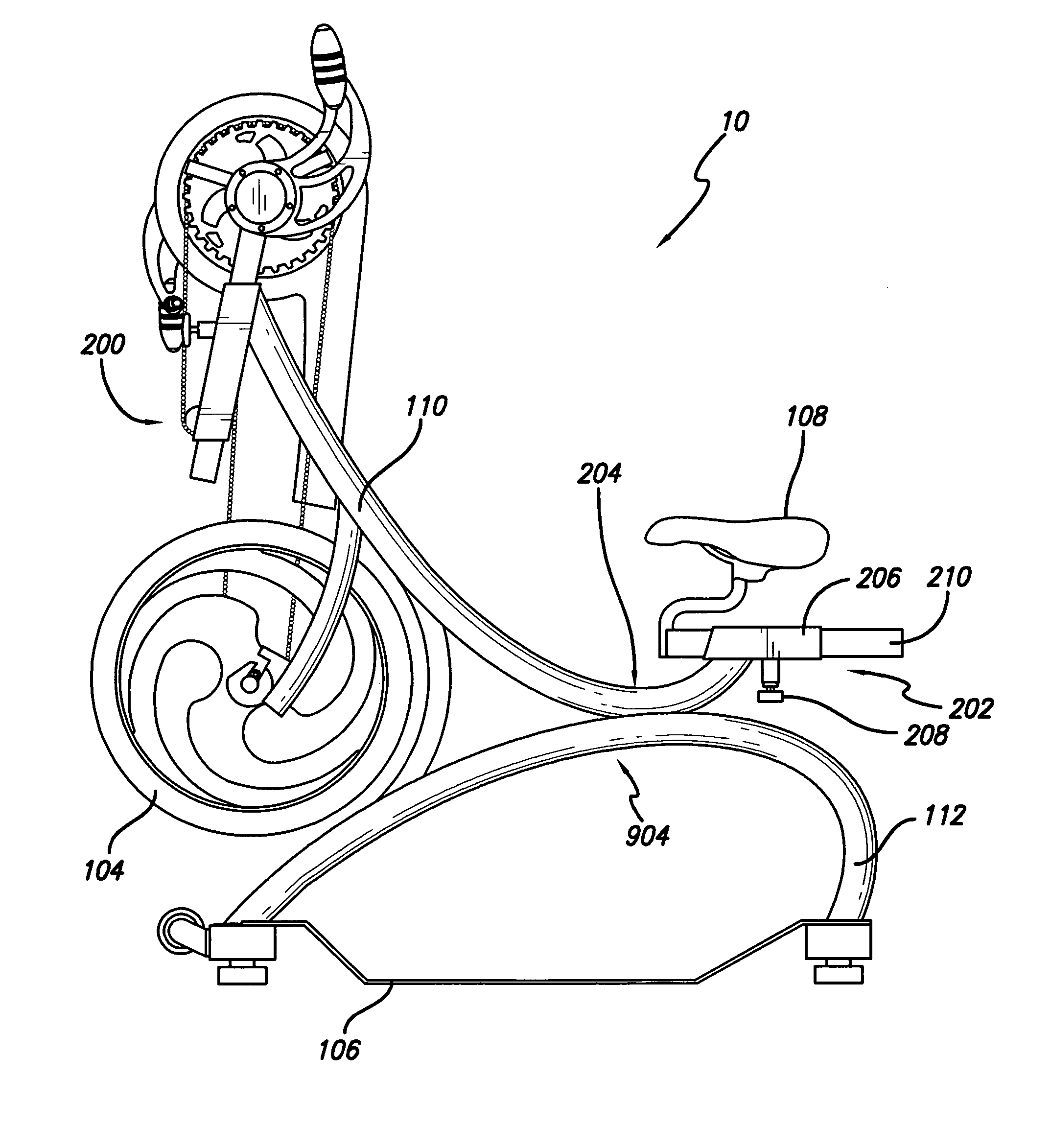
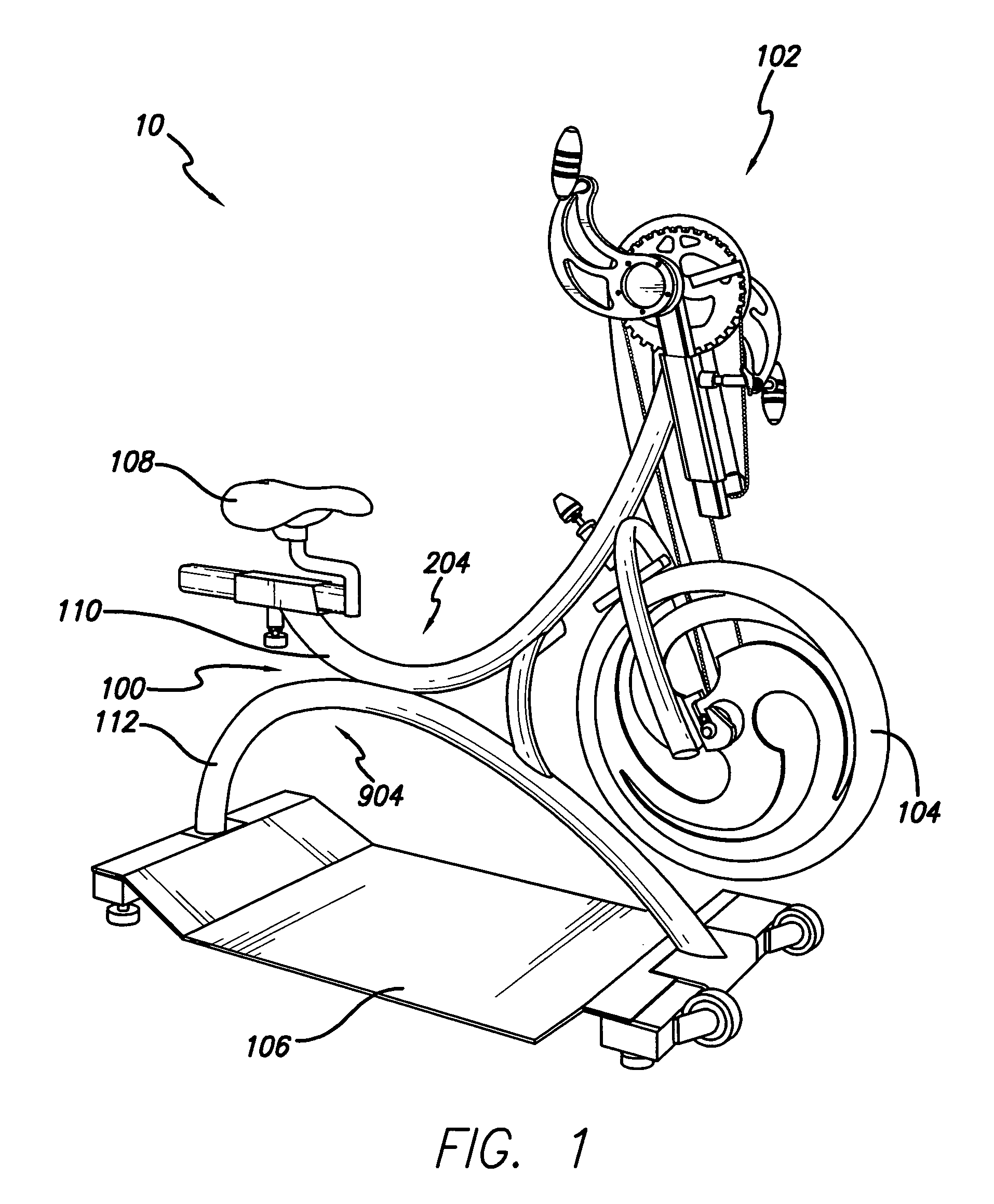
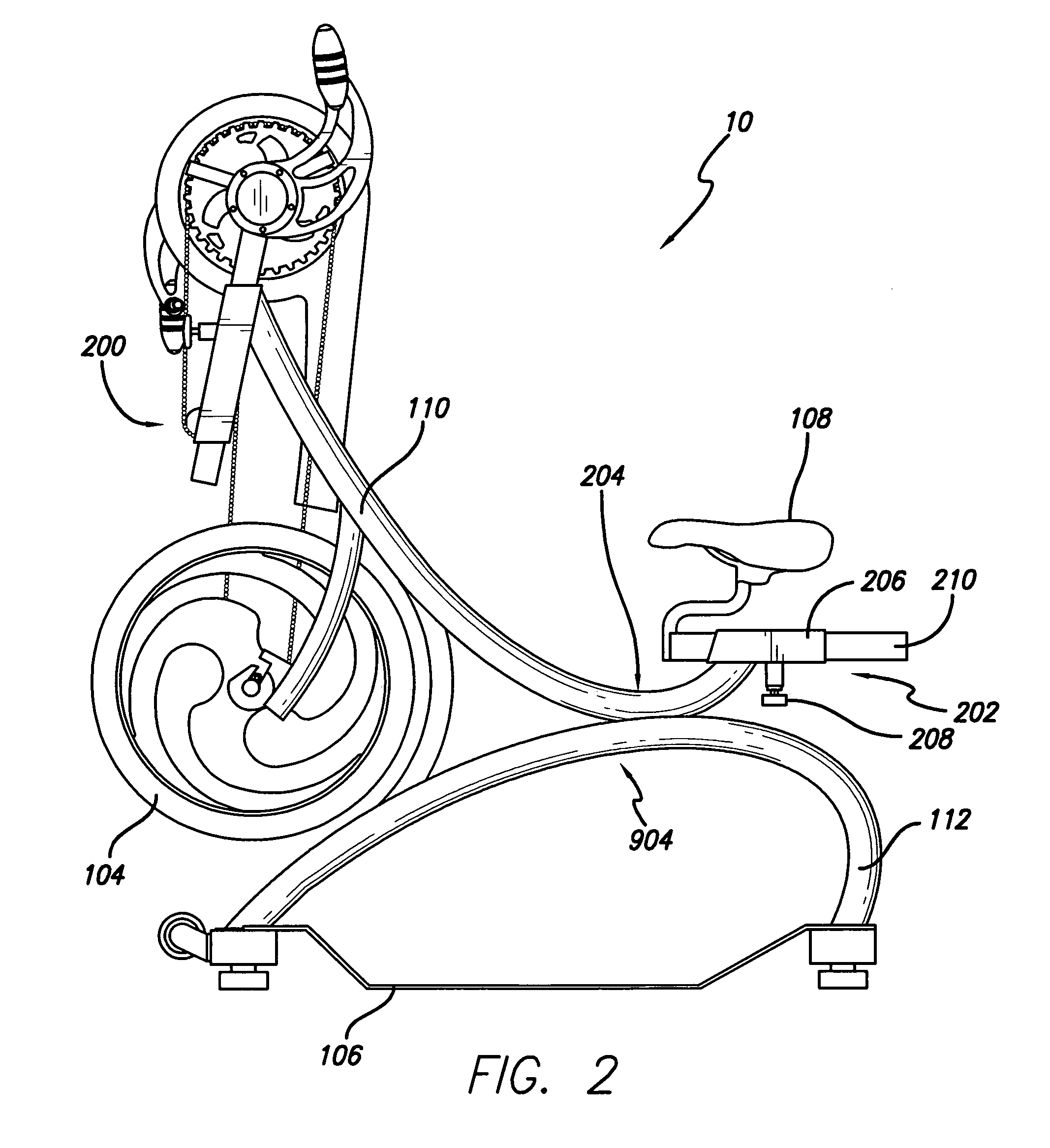
[0027]As shown in FIGS. 1 and 2, the present invention is an exercise cycle 10 for the upper-body comprising a base frame 100, a crank assembly 102, and a flywheel 104 such that the base frame 100 supports the crank assembly 102 and the flywheel 104, the crank assembly 102 drives the flywheel 104, and the flywheel 104 provides resistance to the crank a...


PUM


Abstract

An upper body exercise cycle comprising crank arms that may independently drive a flywheel, which provides resistance to the crank arms, an adjustable headstock and seat to accommodate users of different sizes and isolate different muscle groups, and a base plate ramp to provide support for the feet and to facilitate transportation of the upper body exercise cycle.

Description

CROSS-REFERENCE TO RELATED APPLICATION[0001]This patent application claims the benefit of U.S. Provisional Patent Application Ser. No. 60 / 920,257, filed Mar. 26, 2007, entitled “Upper Body Exercise Cycle.”BACKGROUND OF THE INVENTION[0002]1. Technical Field[0003]This invention relates to exercise equipment.[0004]2. Background Art[0005]There are numerous exercising devices, and in particular, a number of exercise cycles. Most exercise cycles, however are designed to condition the legs. There are exercise cycles designed to exercise the arms as well. However, most of these exercise cycles have dependent crank arms such that rotation of one crank arm causes rotation of the other crank arm. Some exercise cycles have independent crank arms but require two chains either attached to the same wheel or to two different wheels. Thus, there exist a need for an exercise cycle to workout the upper body with independently rotating crank arms, such that a user may exercise each arm independently or...

Claims


Application Information

Patent Timeline
Patent Type & Authority Patents(United States)
IPC IPC(8): A63B22/12
CPCA63B21/225A63B22/0002A63B22/0605A63B21/015A63B2022/0005A63B2022/0041A63B2022/0617A63B2208/0204A63B2208/0233A63B2225/09A63B22/0005
Inventor GOLDBERG, JOHNNY
Owner JOHNNY G METHOD
Learn More