
Coaxial cable connector with electrical ground

a technology of coaxial cable and grounding screw, which is applied in the direction of coupling device connection, connection contact member material, coupling protective earth/shielding arrangement, etc., can solve the problem of much more difficult to un-thread the grounding screw from the lug

Inactive Publication Date: 2010-07-20
CORNING OPTICAL COMM LLC
View PDF23 Cites 36 Cited by
  • Summary
  • Abstract
  • Description
  • Claims
  • Application Information

AI Technical Summary

Benefits of technology

"The present invention is a coaxial cable connector that includes a body portion with a prepared end for connecting to a coaxial port. The connector also has a nut rotatably secured to the body portion for securing the connector to the port. The connector has a post with a lug that extends within the connector for securing a grounding wire. The lug has a first hole for receiving the grounding wire, and a clamp element communicates with the first hole for clamping the grounding wire. The clamp element secures the grounding wire within the first hole of the lug. The lug may also be secured to the compression ring or the body portion of the connector. The invention also includes a break-away head for securing the grounding wire within the lug, and a deformable lug that retains the grounding wire in physical and electrical contact with the connector. The technical effects of the invention include secure and reliable grounding of the coaxial cable connector, prevention of unauthorized removal of the grounding wire, and improved electrical performance."

Problems solved by technology

Once the head of the grounding screw breaks off, it is much more difficult to un-thread the grounding screw from the lug.

Method used


Image

  • Coaxial cable connector with electrical ground
  • Coaxial cable connector with electrical ground
  • Coaxial cable connector with electrical ground

Examples


Embodiment Construction

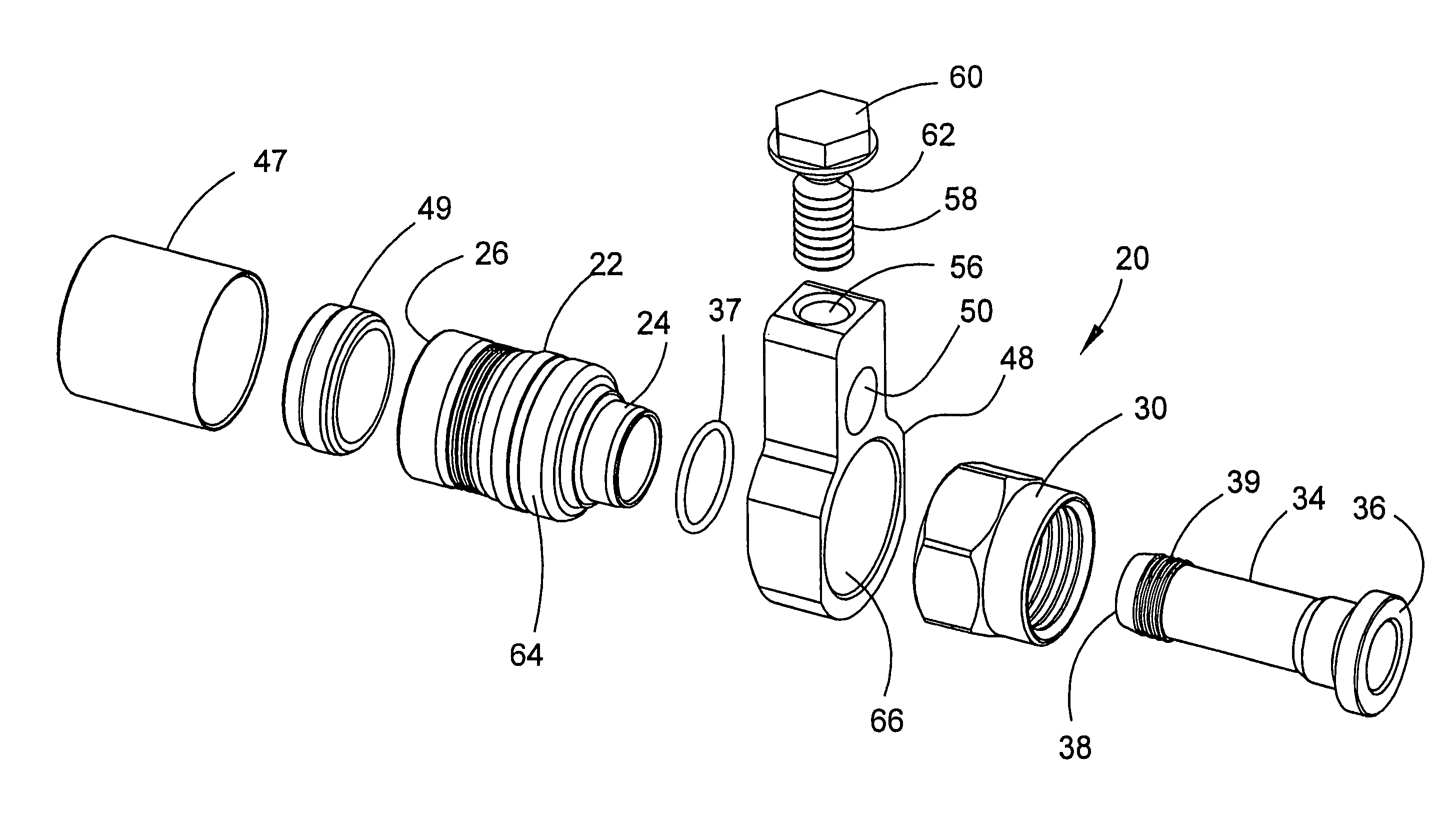
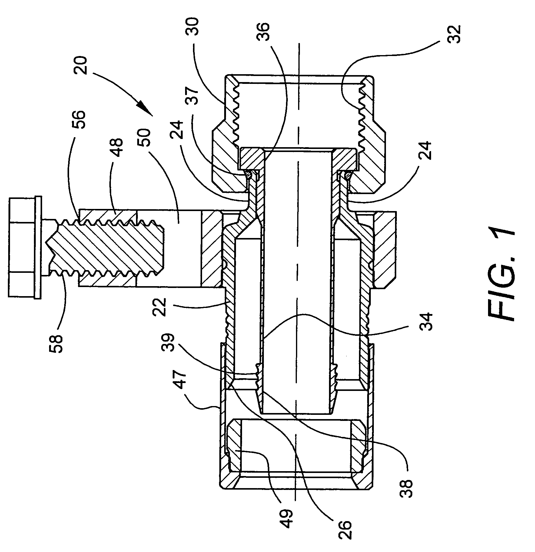
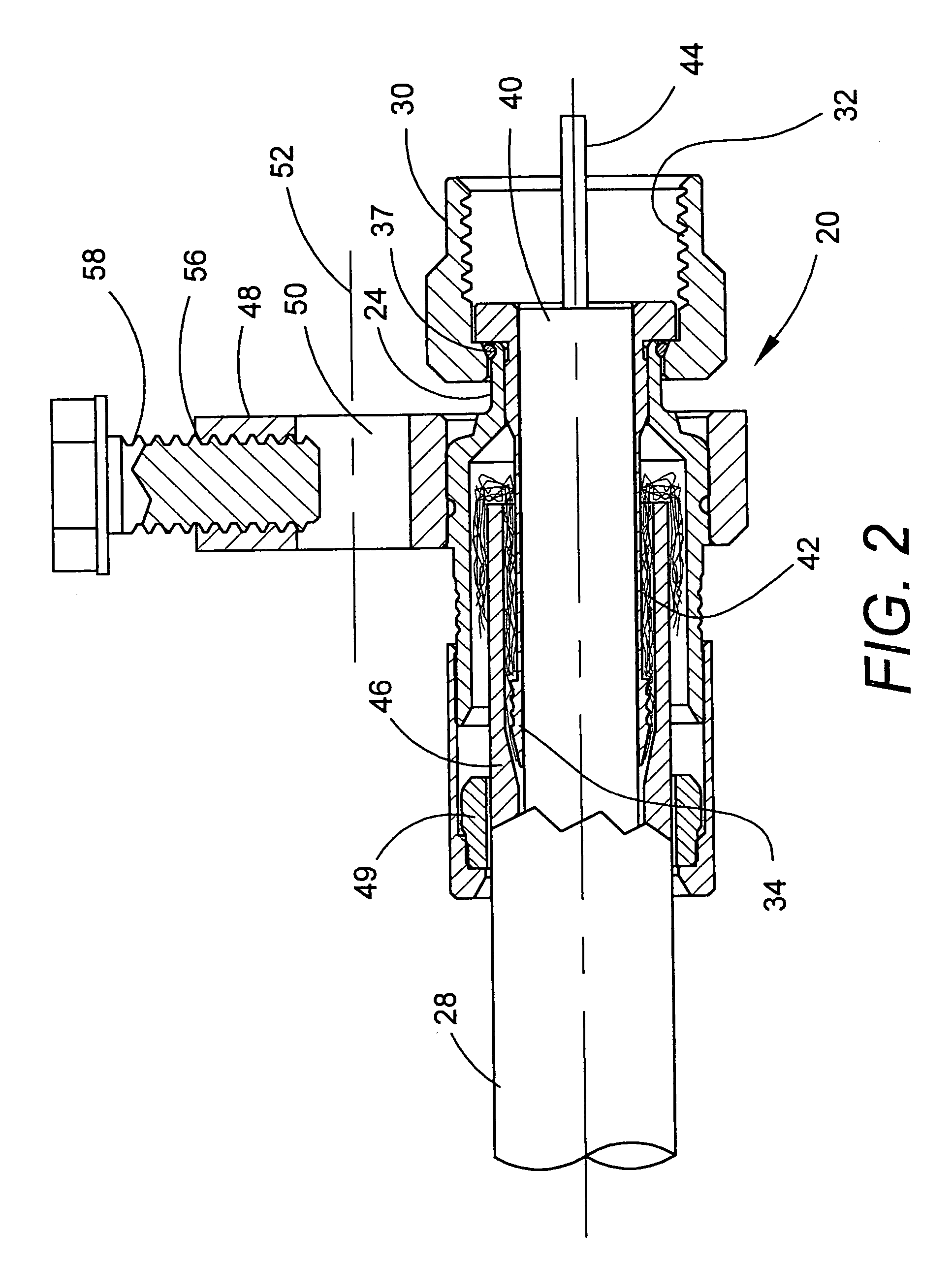
[0033]Referring to FIGS. 1-3 and FIG. 8, a coaxial cable connector, designated generally by reference numeral 20, is shown having a grounding lug. Connector 20 includes a generally-cylindrical body portion 22 having first end 24 and and opposing second end 26. Second end 26 is adapted to receive the prepared end of a coaxial cable 28 (see FIGS. 2 and 3). Body portion 22 is made of metal, is electrically conductive, and in a preferred embodiment, is made from brass.

[0034]Connector 20 also includes a coupler 30, shown as a nut, rotatably secured about first end 24 of body portion 22 for securing coaxial cable connector 20 to a mating coaxial port (not shown), such as an equipment port of a terminal box. Coupler 30 is internally threaded, the internal threads being designated by reference numeral 32. While coupler 30 is illustrated as a conventional internally-threaded nut of the type commonly used for a so-called “F-connector”, nut 30 could also be a BNC coupler or similar type of fas...


PUM


Abstract

A coaxial cable connector includes a bonding block lug for receiving a grounding wire. The connector includes a body portion for receiving the end of a cable, a nut for securing the connector to a mating coaxial port, a post extending within the body portion for extending into the cable, a lug secured to the body portion and having a first hole for receiving the grounding wire, and a clamp element for clamping the grounding wire within the lug. The lug may include a second hole that intersects the first hole. The clamp element may be a set screw, press-fit pin, or the like extending within the second hole for selectively engaging the grounding wire. The set screw may incorporate security features to prevent removal of the grounding wire. The bonding block lug can be incorporated within a variety of connectors, including axially-compressed connectors.

Description

CROSS-REFERENCE TO RELATED APPLICATIONS[0001]This application claims the benefit of priority under 35 U.S.C. §119(e) to U.S. Provisional Application Ser. No. 60 / 690,642 filed on Jun. 14, 2005, the content of which is relied upon and incorporated herein by reference in its entirety.BACKGROUND OF THE INVENTION[0002]1. Field of the Invention[0003]The present invention relates generally to coaxial cable connectors and bonding blocks used to connect a ground lead of the coaxial cable system to a source of ground.[0004]2. Technical Background[0005]Certain coaxial cable applications, such as cable television (CATV) systems, require that the coaxial cable system be coupled to an electrical ground to safely conduct high voltages, resulting from lightning strikes or the like, to ground, and thereby avoid damage to the coaxial cable system. Bonding blocks are often used to attach coaxial cable connectors to a grounding source such as a copper wire terminated to ground. Current bonding blocks a...

Claims


Application Information

Patent Timeline
Patent Type & Authority Patents(United States)
IPC IPC(8): H01R13/648
CPCH01R4/646H01R9/0512H01R9/0524H01R4/36H01R13/6584H01R13/6593
Inventor BURRIS, DONALD ANDREWKISLING, BRIAN LYLELUTZ, WILLIAM BERNARDMILLER, THOMAS DEWEY
Owner CORNING OPTICAL COMM LLC
Learn More