
Prewired electrical apparatus having quick connect components

a technology of pre-wired electrical equipment and components, which is applied in the direction of electrical apparatus casings/cabinets/drawers, gaseous cathodes, coupling device connections, etc., can solve the problems of electrical circuitry installation, time-consuming and labor-intensive renovation of existing structures, and high construction costs, so as to reduce construction costs, reduce the possibility of miswiring the circuit, and install more quickly and easily

Inactive Publication Date: 2005-03-22
SCHULTZ JAMES DOUGLAS +3
View PDF43 Cites 123 Cited by
  • Summary
  • Abstract
  • Description
  • Claims
  • Application Information

AI Technical Summary

Benefits of technology

Advantageously, the various embodiments of the power distribution system can be installed more quickly and easily, thereby reducing costs of construction and reducing the possibility of miswiring the circuit. Also, the embodiments of the power distribution system can be used in a wider variety of construction applications.

Problems solved by technology

Building construction can be expensive and time consuming because buildings are often large and because a multitude of complex tasks must often be completed.
Also, renovating an existing structure can be especially expensive and time consuming for the same reasons.
One time consuming task performed during construction is electrical circuitry installation.
Unfortunately, several inherent problems are associated with this conventional method of electrical system installation.
First, this method of electrical system installation is unduly time consuming, mainly because the electrician works-both before and after the drywall is installed.
Therefore, since most electricians are paid by the hour and are among the highest paid skilled laborers, electrical system installation can be very expensive.
In addition, the current prior art installation requires skilled, highly compensated electricians to install the junction devices.
As such, labor costs associated with such installation is high as compared to labor costs associated with unskilled labor.
Relatedly, if at a later date, the building owner wishes to change a junction device that is already installed, an electrician typically must be called on to change the junction device, and the building owner disadvantageously pays the higher labor costs for the skilled laborer.
Further, connecting and / or splicing wires using wire nuts may leave conductive material of the wires exposed.
This condition may go unnoticed by the electrician during initial electrical testing, but may become more pronounced over time.
Since the wires inside the junction boxes lie in close proximity, a short circuit or even a fire may result.
Thus; this standard method of electrical system installation can produce unfit and unsafe electrical connections.
As the number of wires increases, the possibility that the electrician might incorrectly interconnect or splice the wires increases.
Unfortunately, if the components are incorrectly wired, the electrician must spend costly time re-wiring.
Relatedly, complex circuitry may not be able to fit inside a conventional junction box because of the number of wires and wire screws involved.
In this case, a larger and more expensive junction box is disadvantageously used.
Several devices have addressed these concerns with limited degrees of success.
However, the device disclosed in the Figart patent does not solve all problems associated with the prior art.
For instance, the junction device is attached to the junction box via a plurality of screws, and threading the screws of the junction device to the junction box can be overly time consuming and expensive considering the fact that the electrician will likely complete this task.
Although this connection method may be quicker than other methods, stab-in connections may be insufficient for some applications.
However, the Figart device fails to disclose such a connection means.

Method used


Image

  • Prewired electrical apparatus having quick connect components
  • Prewired electrical apparatus having quick connect components
  • Prewired electrical apparatus having quick connect components

Examples


Embodiment Construction

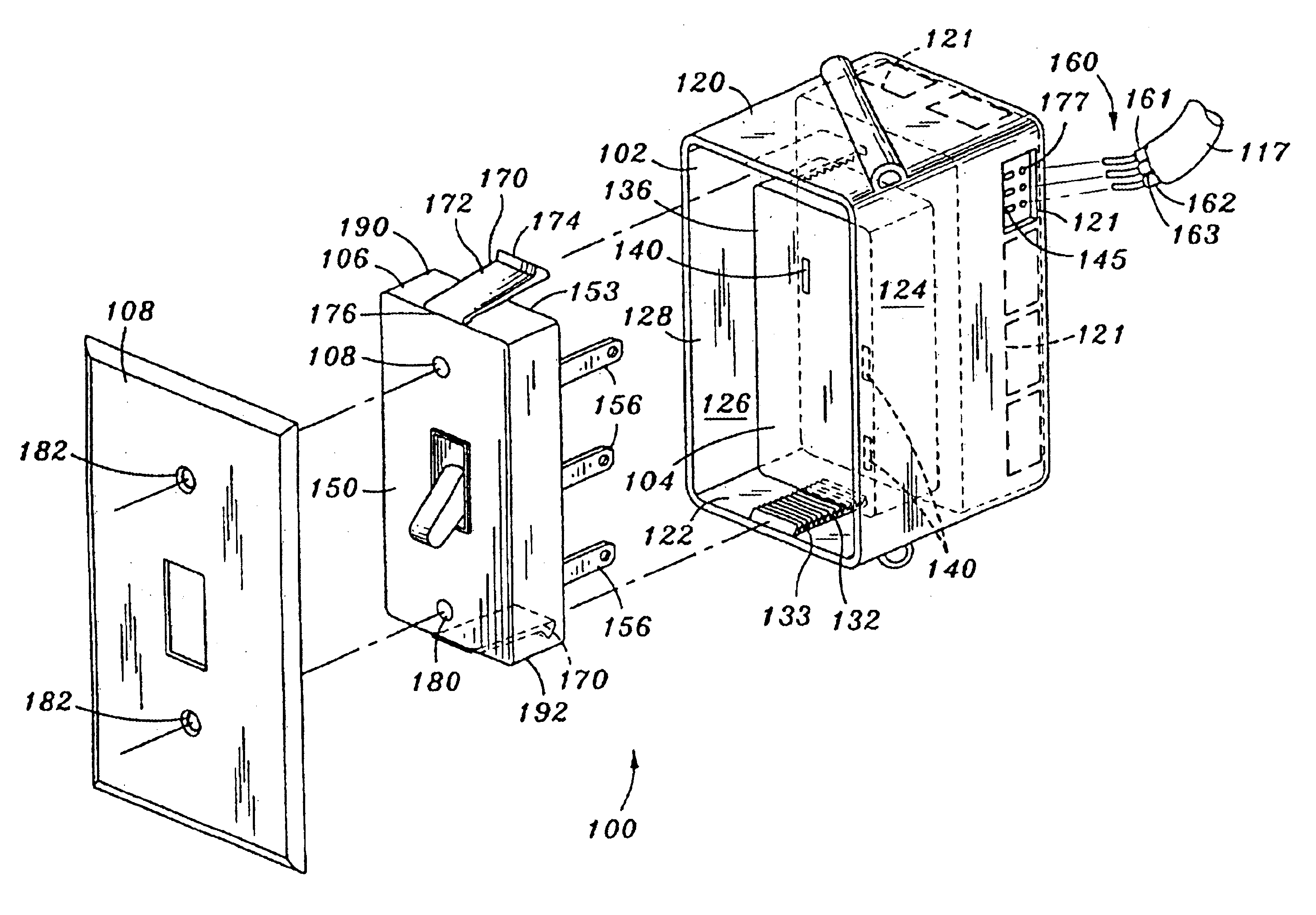
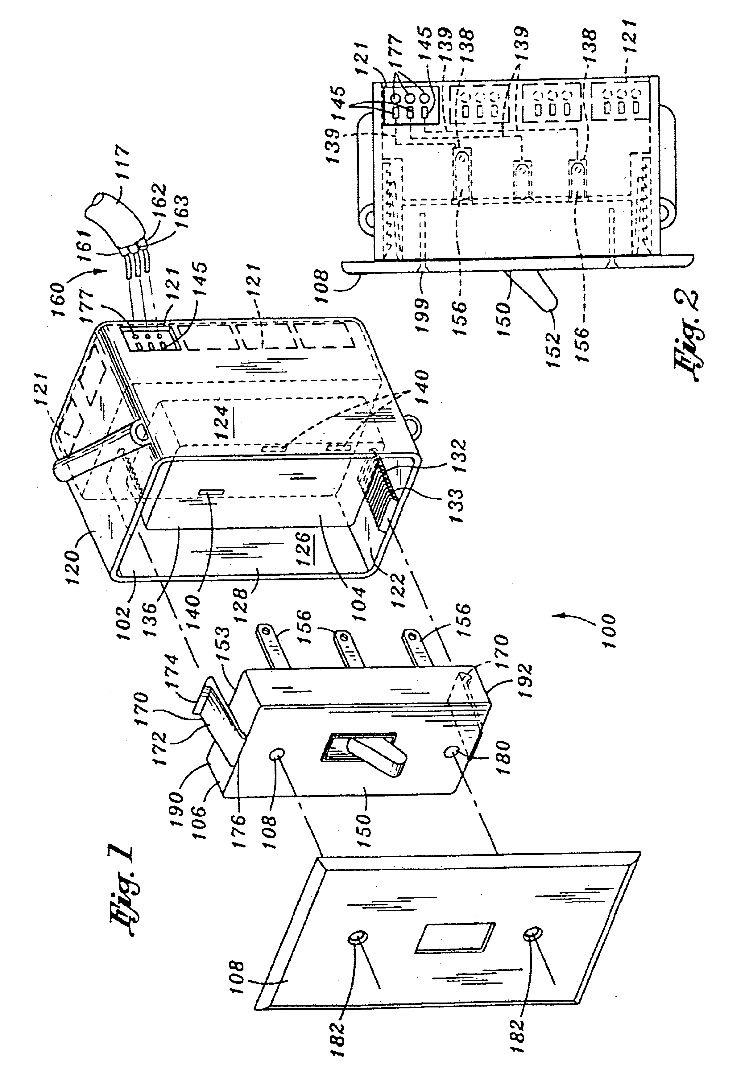
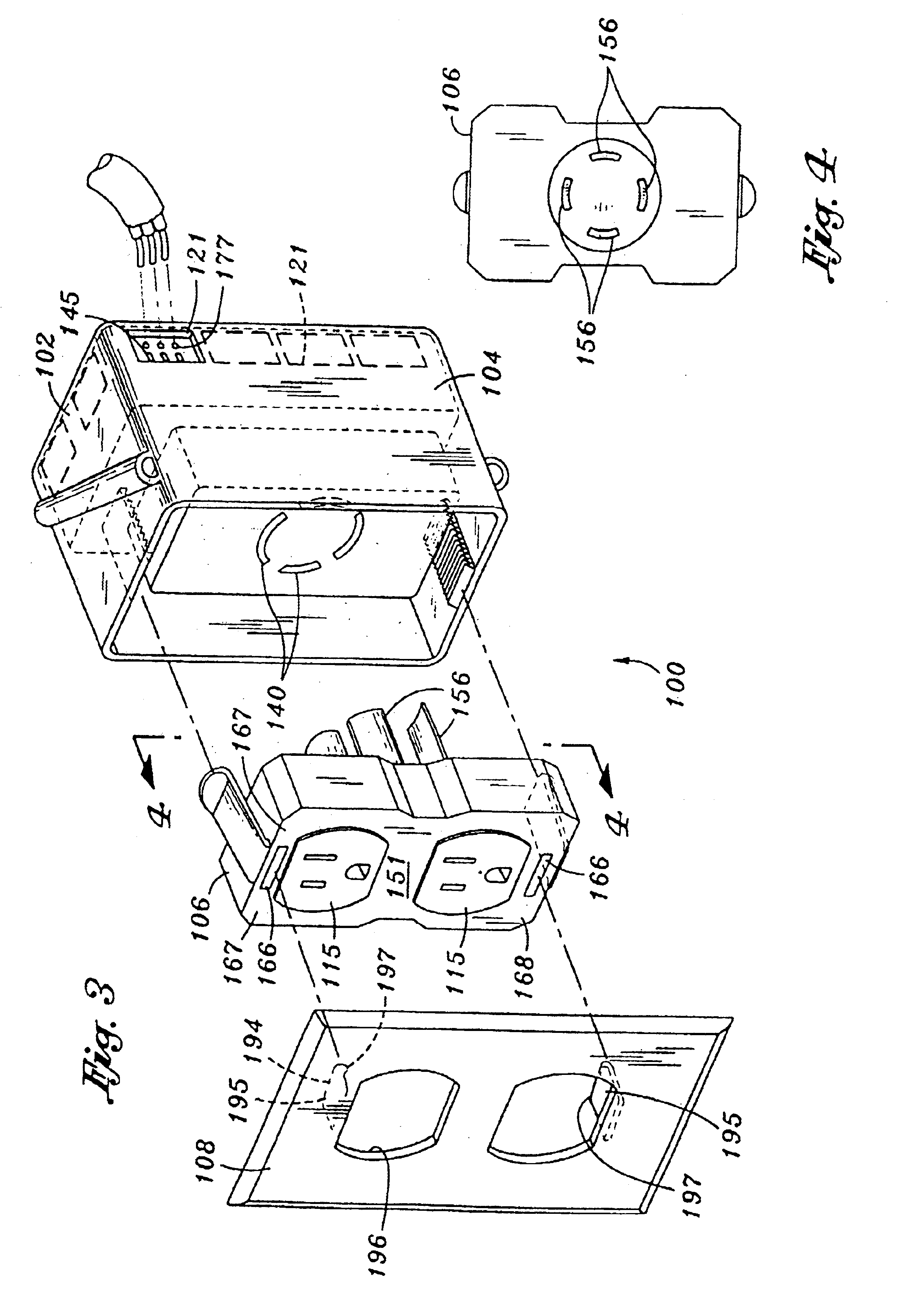
Referring now to the drawings wherein the showings are for purposes of illustrating preferred embodiments of the present invention only, and not for purposes of limiting the same, FIGS. 1 and 2 illustrate one embodiment of a power distribution system 100. As shown, the power distribution system 100 comprises a junction box 102, with a wiring hub 104 positioned therein. The power distribution system 100 also comprises a junction device 106 (i.e., a switch, duplex plug, dimmer, etc.) and a cover plate 108.

As will be described in greater detail below, a plurality of wires 160 can be quickly connected electrically to the hub 104 through the junction box 102. In one embodiment, color coding is included on the junction box 102 that indicates correct wire placement and advantageously-ensures proper wiring of the circuit.

Furthermore, as will be described in greater detail, the junction device 106 can be structurally connected to the junction box 102 via interference there between. This adva...


PUM


Abstract

A power distribution system, suitable for use in a building, comprising a junction box, a hub, a junction device, and a cover plate. Wiring from the building is connected to the hub using alternative means such as stab-in connections, set screws, or loop screws, and color coding facilitates proper wiring. Also, the junction device is a modular piece that can be attached to the junction box via interference there between. Furthermore, a cover plate can be attached to the junction device via interference there between, or the cover plate can be integrally attached to the junction device. One embodiment of the hub accommodates circuitry that functions with the junction device while simultaneously accommodates circuitry wholly independent of the junction device. As such, the power distribution system enables wiring to be completed more quickly and accurately, in a wider variety of applications, thereby advantageously reducing associated costs.

Description

STATEMENT RE. FEDERALLY SPONSORED RESEARCH / DEVELOPMENT(Not Applicable)BACKGROUND OF THE INVENTIONThe present invention relates generally to electric circuit components and more particularly to switches, receptacles, and other junction components which can be quicky and safely installed, thereby advantageously reducing the time and cost associated with an electrician's services.Building construction can be expensive and time consuming because buildings are often large and because a multitude of complex tasks must often be completed. Also, renovating an existing structure can be especially expensive and time consuming for the same reasons.One time consuming task performed during construction is electrical circuitry installation. Conventionally, an electrician positions junction boxes on the exposed studs of the building at pre-determined locations throughout the building. These junction boxes will eventually hold junction devices such as switches and outlets as will be described in gr...

Claims


Application Information

Patent Timeline
IPC IPC(8): H02G3/14H02G3/08H01H1/58H01H1/00H01H9/02
CPCH01R24/70H02G3/14H02G3/086H01H1/5866H01R2103/00H01R24/76H01R27/00
Inventor SCHULTZ, JAMES DOUGLASWEBER, MICHAEL HENRYPETRAK, GARY LEESHAW, RONALD D.
Owner SCHULTZ JAMES DOUGLAS
Learn More