Binding device for files and binders

a technology for a file and a binder, which is applied in the field of binding devices, can solve the problems of large file cover, inability to close, and inconvenient passing of the binding holes of a large number of objects, and achieve the effect of relatively easy and stable formation

Inactive Publication Date: 2010-07-20
LIHIT LAB INC
View PDF9 Cites 0 Cited by
  • Summary
  • Abstract
  • Description
  • Claims
  • Application Information

AI Technical Summary

Benefits of technology

[0013]According to preferred embodiments of the present invention, a binding device is provided in which a ring to be inserted into a binding hole of an object to be bound is openably and closeably secured to a base plate so as to be opened and closed by an opening-closing mechanism including a rotationally movable lever. In the binding device, a first ring member having a semi-annular binding ring portion and a second ring member having a semi-annular binding ring portion, which define the binding ring, are pivotally supported at respective pivot portions at respective lower ends thereof on the base plate. Furthermore, a junction at an end opposite to the pivot portion of the binding ring portion of the first ring member and a junction at an end opposite to the pivot portion of the binding ring portion of the second ring member are joined together at the center between the pivot portions of the first ring member and the second ring member, whereby the binding ring portion of the first ring member and the binding ring portion of the second ring member provide a ring-like shape which defines a closed loop. Moreover, the first ring member and the second ring member are arranged to be interlocked with the opening-closing mechanism including the lever so as to be opened and closed about the respective pivot portions provided in the lower ends thereof by rotationally moving the lever. In addition, the base plate is provided with a lever shaft receiver for pivotally supporting the lever of the opening-closing mechanism, and the lever shaft receiver is formed by punching the base plate and bending the punched portion upwardly. Therefore, the lever shaft receiver is formed relatively easily and stably using only a single base plate.

Problems solved by technology

However, since each arch portion has a shape such that the end thereof points downward even when each of the rings is opened, it is very inconvenient to pass the binding holes of a large number of objects to be bound such as paper sheets toward the arch portion side.
However, in this configuration, when the arch portion of each of the rings is opened, the arch portion touches the lever since it is not sufficiently opened.
Moreover, in lever arch files, a binding device is provided not on the spine of the cover but on the side B since when bound paper sheets are present in pole-like portions, the cover on the side B cannot be closed.
Thus, the width of the cover of the files is large, and there is an inconvenience that the storage space for the files is large.

Method used


Image

  • Binding device for files and binders
  • Binding device for files and binders
  • Binding device for files and binders

Examples


Embodiment Construction

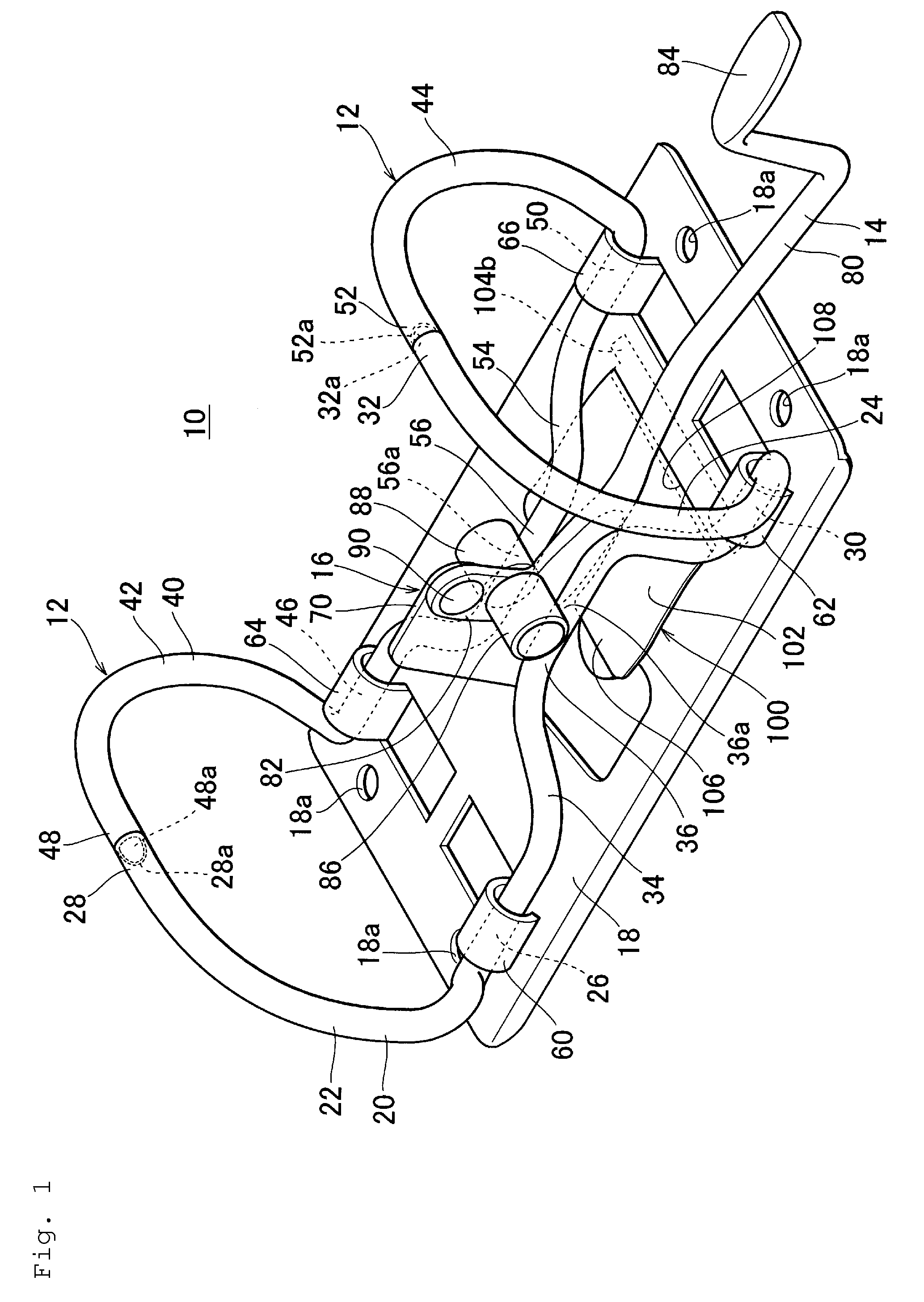
[0066]FIG. 1 is a perspective view of a binding device of a preferred embodiment of the present invention.

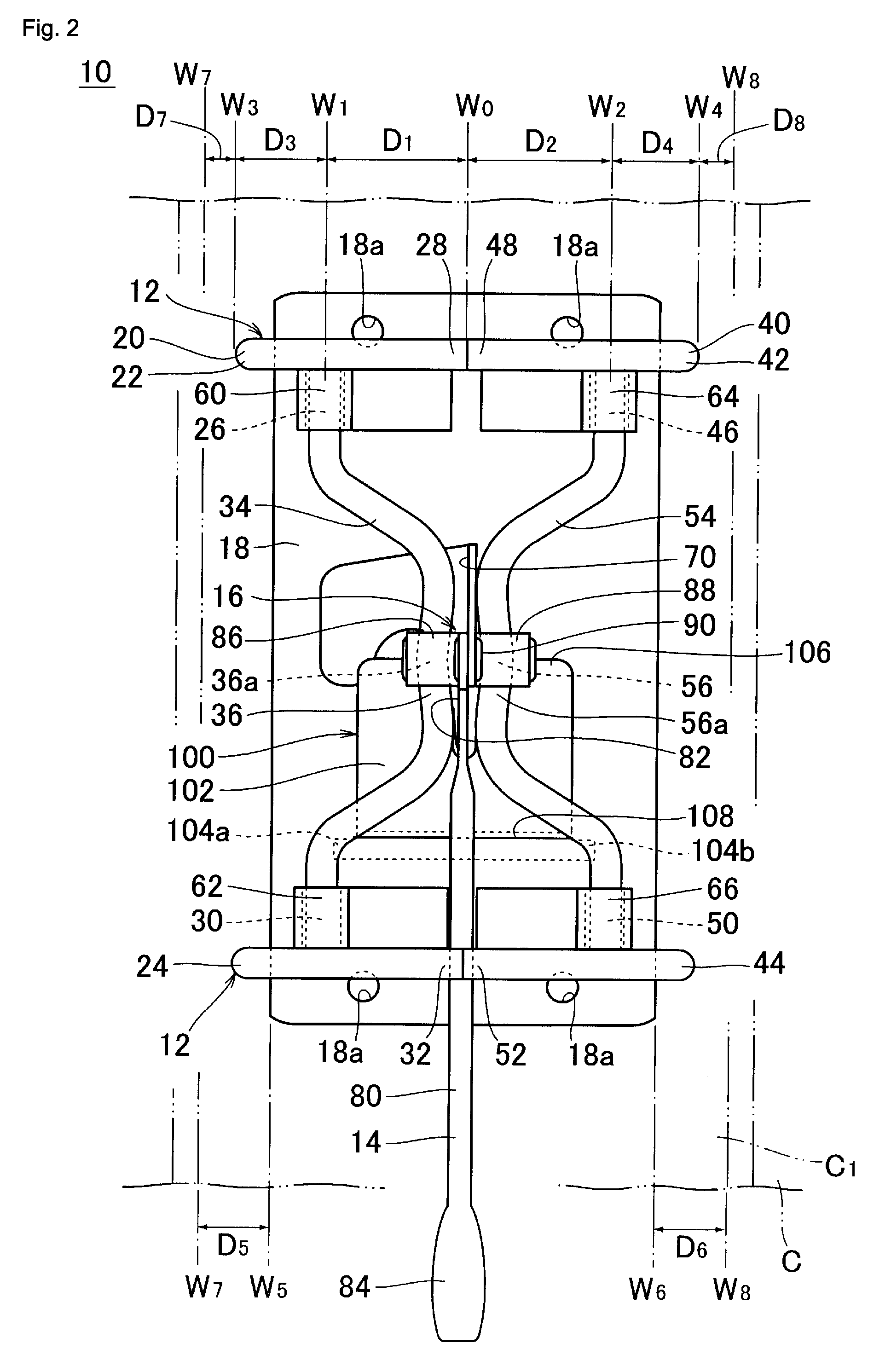
[0067]FIG. 2 is a plan view of the binding device shown in FIG. 1.

[0068]FIG. 3 is a left side view of the binding device shown in FIG. 1.

[0069]FIG. 4 is a rear view of the binding device shown in FIG. 1.

[0070]FIG. 5 is a front view of the binding device shown in FIG. 1.

[0071]FIG. 6 is a perspective view illustrating the operating state of the binding device shown in FIG. 1.

[0072]FIG. 7 is a left side view illustrating the operating state of the binding device shown in FIG. 1.

[0073]FIG. 8 is a perspective view illustrating the operating state of the binding device shown in FIG. 1.

[0074]FIG. 9 is an exploded perspective view being a right side view of the binding device shown in FIG. 1.

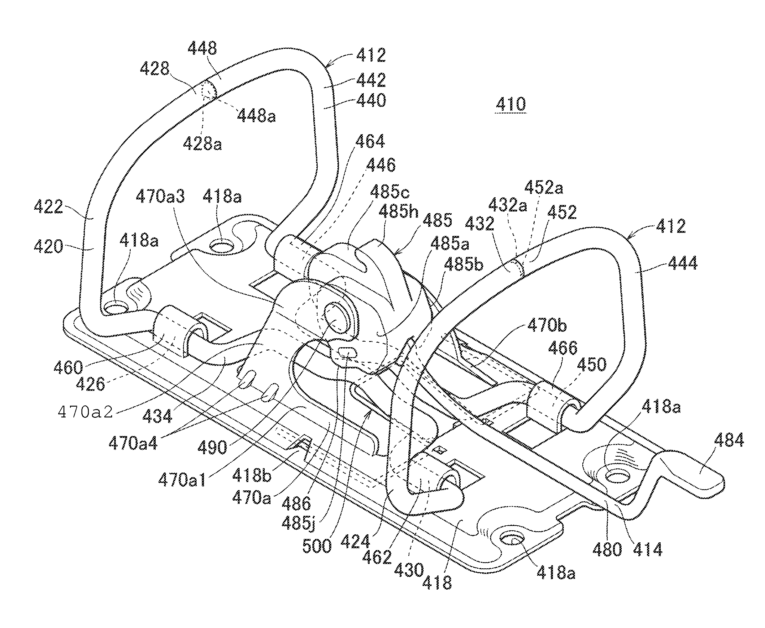
[0075]A binding device 10 is a binding device for files and binders, and in particular, is a binding device for use in A-Z files. In this binding device 10, binding rings 12 to be inserted into bind...


PUM


Abstract

A binding device for files and binders includes rings to be inserted into binding holes of an object to be bound which are openably and closeably secured to a base plate so as to be opened and closed by an opening-closing mechanism including a rotationally movable lever. In the binding device, a first ring member and a second ring member defining the binding rings are configured such that they are interlocked with the opening-closing mechanism including the lever so as to be opened and closed about respective pivot portions provided in the lower end thereof by rotationally moving the lever. The base plate is provided with a lever shaft receiver for pivotally supporting the lever of the opening-closing mechanism, and the lever shaft receiver is formed by punching the base plate and bending the punched portion upwardly.

Description

BACKGROUND OF THE INVENTION[0001]1. Field of the Invention[0002]The present invention relates to a binding device for holding objects to be bound, such as documents, in a file or a binder. In particular, the invention relates to a binding device for files and binders which is suitable for use as a binding device for so-called A-Z files and which holds objects to be bound such as documents using rings that are opened and closed by a mechanism including a lever.[0003]2. Description of the Related Art[0004]Lever arch files called A-Z files are widely known as files configured such that objects to be bound, such as documents, are held in the files by passing rings through respective binding holes provided near an edge of the objects.[0005]Generally, a lever arch file includes a base and two rings which are firmly attached to the base and extend upwardly and which are inserted into respective holes provided in objects to be bound, such as documents. Each of the rings includes an arch por...

Claims


Application Information

Patent Timeline
Patent Type & Authority Patents(United States)
IPC IPC(8): B42F13/20
CPCB42F13/22
Inventor TANAKA, KANJIARAI, HIROSHIARIMOTO, YOSHITERU
Owner LIHIT LAB INC
Why Eureka
Try Eureka