
Highly fault-tolerant method for evaluating phase signals

a phase signal and fault-tolerant technology, applied in the direction of noise figure or signal-to-noise ratio measurement, instruments, electrical/magnetic diameter measurement, etc., can solve the problems of large errors in the output signal and the inability of evaluation methods to function correctly, so as to reduce the unambiguous range, robust evaluation, and reduce the effect of uncertainty

Inactive Publication Date: 2010-07-06
ROBERT BOSCH GMBH
View PDF9 Cites 1 Cited by
  • Summary
  • Abstract
  • Description
  • Claims
  • Application Information

AI Technical Summary

Benefits of technology

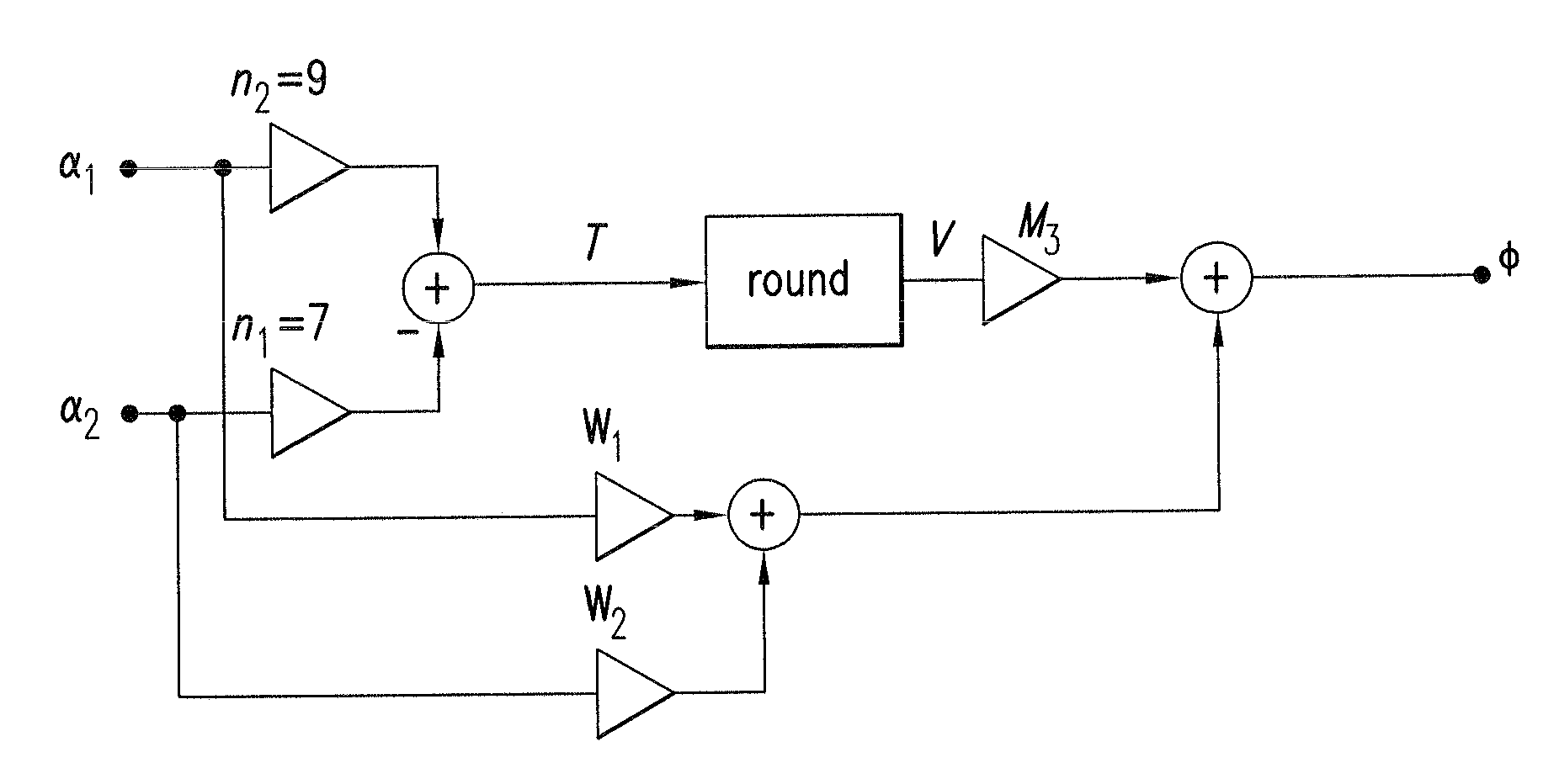
[0017]The basic point of the present invention is to be able to use the phase evaluation known as the modified vernier method to unambiguously determine a physical parameter Φ even with systems that have considerable faults in the input signals.
[0018]If the periodicity values are established by the system or the basic physical conditions, the present invention results in a more robust evaluation than with the known methods. The reduction in unambiguous range E associated therewith to a reduced unambiguous range Ered can often be tolerated.
[0019]The inventive method has the advantage that its robustness is multifold greater than that of evaluation methods known in the related art. The increase in the robustness of the evaluation method is attained essentially at the expense of unambiguous range E, which is decreased in size to reduced unambiguous range Ered. In reduced unambiguous range Ered, however, much greater limits can be chosen for the assignment of V=V(T) TUk and TOk, thereby increasing the fault tolerance for phase-measured values αi. These limits are typically greater than periodicity difference Δn of periodicity values ni. In this case, “robustness” refers to the tolerance to faults in the phase signals. It is that much greater, the greater the faults in the phase signals are allowed to be, while the evaluation functions correctly.

Problems solved by technology

If the faults exceed this bound, large errors in the output signal can occur.
The result is that the evaluation methods no longer function correctly.

Method used


Image

  • Highly fault-tolerant method for evaluating phase signals
  • Highly fault-tolerant method for evaluating phase signals
  • Highly fault-tolerant method for evaluating phase signals

Examples


Embodiment Construction

[0028]The description of the method applies to systems with two phase signals α1 and α2. It is also possible, in principle, to apply the method to systems with several phase signals αi, with 1≦i≦m, that is, with m dimensions.

[0029]As a prerequisite for the use of the inventive method, there must be an integer periodicity difference Δn=|n2−n1| greater than one. That is, the following applies:

Δn=2, 3, 4, 5, . . .  (II)

[0030]When normalized, the reduced unambiguous range is approximately 1 / Δn. In the case of two-wavelength interferometry with wavelengths λ1 and λ2, this reduced unambiguous essentially corresponds to “synthetic wavelength”Λ, with

[0031]Λ=λ1⁢λ2λ1-λ2.

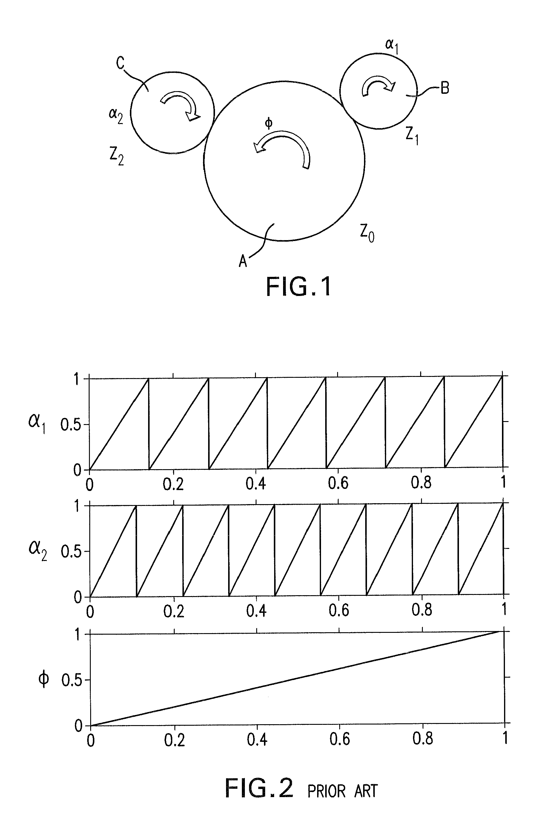
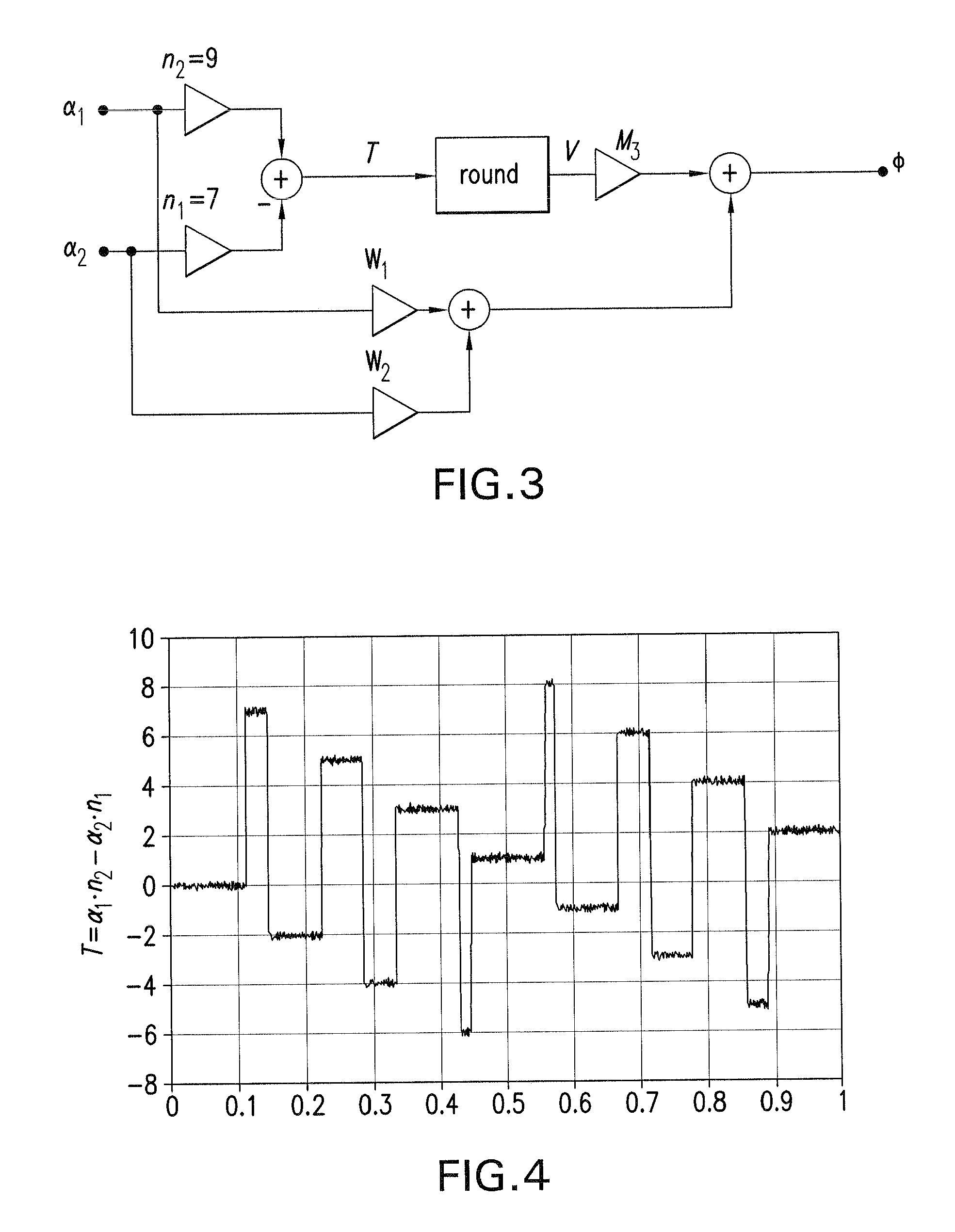
[0032]The method is explained with reference to a system with gears as shown in FIG. 1. The number of teeth Z0, Z1 and Z2 of gears A, B, C are chosen such that periodicities n1=7 and n2=9 result for phase-measured values α1, α2. Unambiguous range E of rotational angles Φ then typically extends over several revolutions of the s...


PUM


Abstract

The invention relates to a method for unambiguously determining a physical parameter Φ using m phase-measured values αi with 1≦i≦m, whereby the phase-measured values αi have different, integer periodicity values ni and an integer periodicity difference (a) with Δn>1 within an unambiguous range E of the physical parameter Φ. A value T with (b) and (c) is calculated based on the phase-measured values αi and the periodicity values ni thereof, and, within a reduced unambiguous range Ered with (d), a value V is allocated to the value T by allocation according to (e), wherein TUk stands for a respective lower limit and TOk for a respective upper limit of T. The allocation intervals between the upper (TOk) and the lower limits (TUk) for T, as wells as the distances (f) correspond at least to the periodicity difference Δn. In order to determine the physical parameter Φ, value V is added up with the phase-measured values αi in a weighted manner.Δ⁢⁢n=ni-ni-1(a)T=T⁡(αj,ni)(b)j,l∈Z⁢{1,…⁢,i}(c)Ered=1Δ⁢⁢n·E(d)V=V⁡(T)={V1⁢f⁢u¨⁢r⁢⁢T≥TO⁢⁢1V2⁢f⁢u¨⁢r⁢⁢TU⁢⁢2≤T<TO⁢⁢2V3⁢f⁢u¨⁢r⁢⁢TU⁢⁢3≤T<TO⁢⁢3…Vk⁢f⁢u¨⁢r⁢⁢T<TUk(e)Δ⁢⁢V=Vk+1-Vk(f)

Description

CROSS-REFERENCE TO A RELATED APPLICATION[0001]The invention described and claimed hereinbelow is also described in German Patent Application DE 102005033402.4 filed on Jul. 18, 2005. This German Patent Application, whose subject matter is incorporated here by reference, provides the basis for a claim of priority of invention under 35 U.S.C. 119(a)-(d).BACKGROUND OF THE INVENTION[0002]The present invention relates to a method for determining a physical parameter Φ, and circuit design for carrying out the method.RELATED ART[0003]With some technical measurement tasks, two or more phase-measured values are obtained, which are used to determine the physical parameter to be measured, e.g., an angle or a distance. These phase signals pass through several periods over an unambiguous range E of the parameter to be measured, i.e., they are also ambiguous within the unambiguous range E of the parameter to be measured. The number of periods of phase signal αi in unambiguous range E is referred ...

Claims


Application Information

Patent Timeline
Patent Type & Authority Patents(United States)
IPC IPC(8): G06F19/00G01P3/00
CPCG01D5/2452G01D2205/28
Inventor STEINLECHNER, SIEGBERTWENZLER, AXEL
Owner ROBERT BOSCH GMBH
Learn More