
Polychrome rotary press

Inactive Publication Date: 2010-07-06
WINDMOELLER & HOELSCHER GMBH
View PDF26 Cites 3 Cited by
  • Summary
  • Abstract
  • Description
  • Claims
  • Application Information

AI Technical Summary

Benefits of technology

[0014]The objective of the present invention is to improve the accuracy and the quality of this register process.
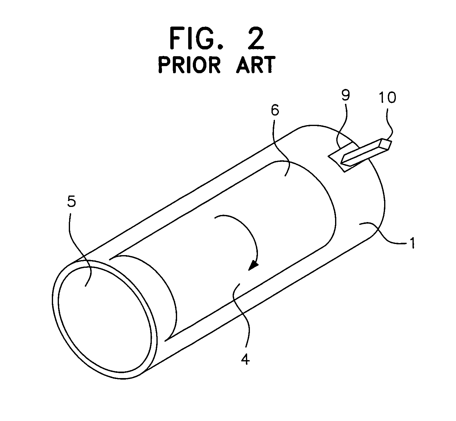
[0016]The measures according to the present invention can effectively prevent the information carriers, for example in case of optical sensors, from getting smudged and consequently resulting in register inaccuracies. The information carriers can get smudged and result in such register inaccuracies even in the case of magnetic or electromagnetic sensors. An additional advantage is that in case of all types of sensors, it is possible to prevent damages to the information carriers resulting from the print and the filling in the print image
[0020]It proves to be advantageous if a control unit carries out said control.
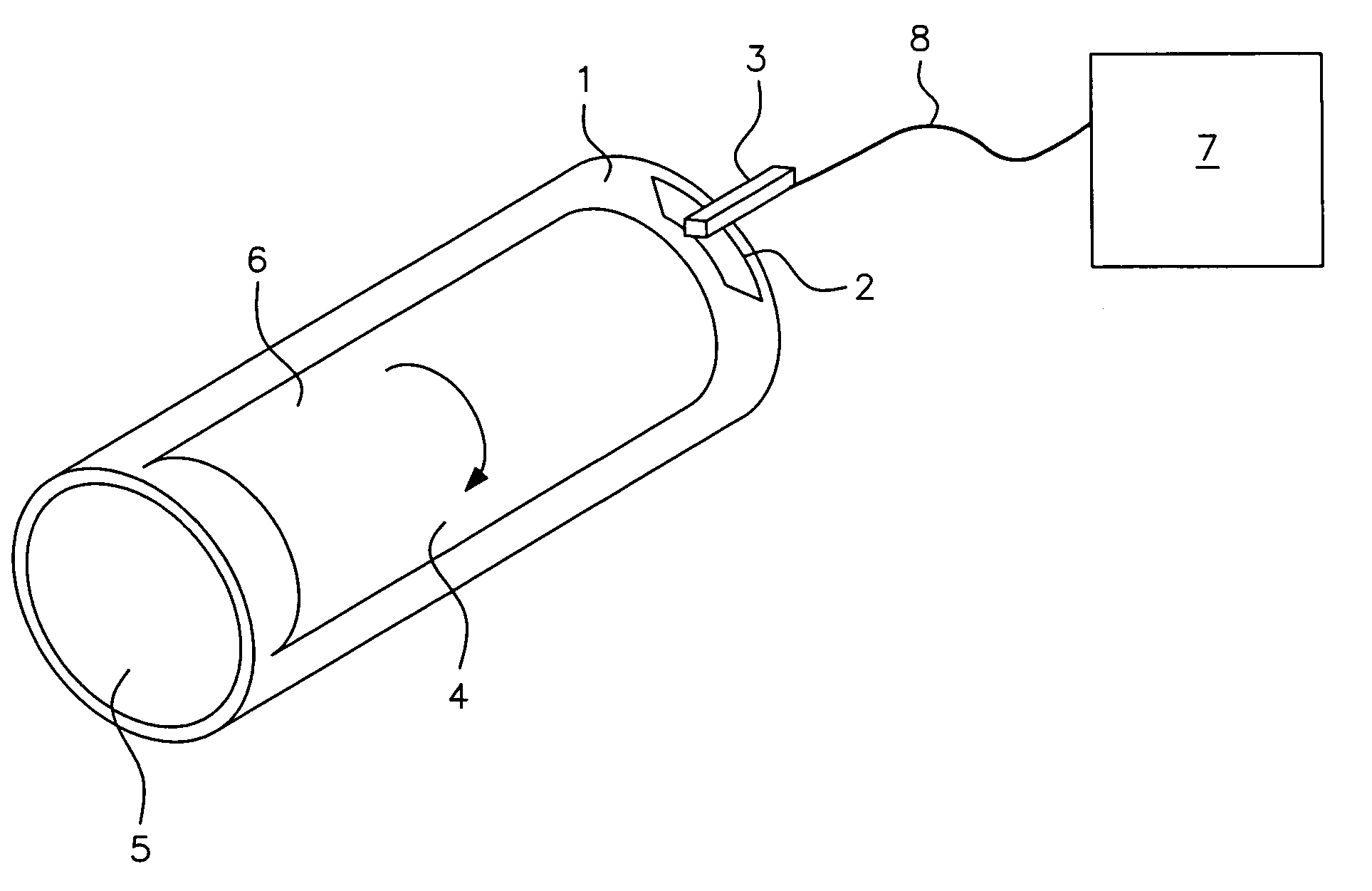
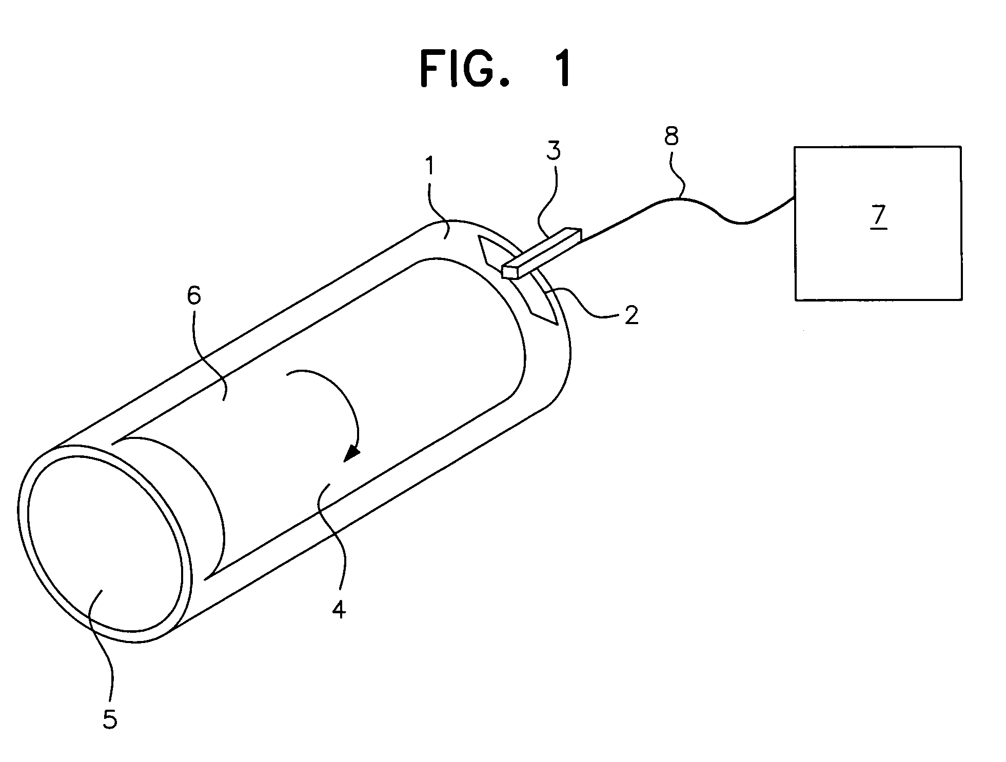
[0025]Preferred types of arrangement of the information carrier have been specified in the dependent claims. As mentioned earlier, information carriers can also be distinct as pronounced markings on the periphery of the printing plate support. Such markings can be present as notches or coloring in the material of the printing plate support and can be detected using optical sensors. However, this purpose can also be achieved by using a metal strip that is fixed in the material of the printing plate support and that can be detected using a suitable electromagnetic sensor. If such simple markings are designed as a line or a point, they can supply a small amount of information during a rotation of the printing plate support. However, this information is basically sufficient for determining the angle position of the printing plate support in the peripheral direction (longitudinal register) and the axial position of the printing plate support on the print cylinder and / or on the mandrel (transverse register). However, information carriers that are stretched over large areas of the peripheral surface in the peripheral direction are preferred. Such information carriers can be loaded with larger amounts of information and it is possible that the sensor can record the exact position of the printing plate over a large angular range of the rotation of the printing plate around the mass centroid axis of the mandrel or the print cylinder. This additional information can benefit the quality of the longitudinal register.

Problems solved by technology

The information carriers can get smudged and result in such register inaccuracies even in the case of magnetic or electromagnetic sensors.

Method used


Image

  • Polychrome rotary press
  • Polychrome rotary press
  • Polychrome rotary press

Examples


Embodiment Construction

[0034]Further scope of applicability of the present invention will become apparent from the detailed description given hereinafter. However, it should be understood that the detailed description and specific examples, while indication preferred embodiments of invention, are given by way of illustration only, since various changes and modifications within the spirit and scope of the invention will become apparent to those skilled in the art from this detailed description.

[0035]FIG. 1 illustrates schematically the arrangement of an embodiment of a printing plate support 1 according to the present invention that has an information carrier 2. In this embodiment, the information carrier is an intentionally shaped magnetic tape 2 that is embedded into the printing plate support 1. However, linear magnetic tapes are usually preferred. The sensor 3 is attached at an appropriate place of the printing machine that is not illustrated here. The sensor 3 is suitable for reading out the magnetic ...


PUM


Abstract

A multi-color rotary printing machine has one printing plate support assigned to the colors that are transferred onto the print substrate. This printing plate support supports a printing plate and is attached to a mandrel or a cylinder of a rotary printing machine in order to transfer the print image onto the print substrate. The rotary printing machine has register devices that determine the position of the printing plates with respect to one another and that have sensors to determine the positions of the printing plate support in the printing machine.

Description

CROSS-REFERENCE TO RELATED APPLICATION[0001]This is a nationalization of PCT / EP04 / 005127 filed May 6, 2004 and published in German.BACKGROUND OF THE INVENTION[0002]1. Field of Invention[0003]The present invention relates to a multi-color rotary printing machine[0004]in which one printing plate support each is assigned to the colors to be transferred onto the print substrate, whereby said printing plate support supports a printing plate and[0005]can be attached to a mandrel or a cylinder of a rotary printing machine in order to transfer the print image onto the print substrate,[0006]whereby the rotary printing machine has register devices that determine the position of the printing plates with respect to one another.[0007]2. Description of the Prior Art[0008]Machines of such type are designed, for example, as flexographic printing machines and gravure printing machines. The term “printing plate support” refers to all possible cylinders, sleeves, or even flexible mats that support a p...

Claims


Application Information

Patent Timeline
IPC IPC(8): B41F13/24B41F33/00
CPCB41F33/0081B41P2233/13Y10S101/36
Inventor KRUEMPELMANN, MARTINLODDENKOETTER, MANFRED
Owner WINDMOELLER & HOELSCHER GMBH
Learn More