
Device for trapping flies

Inactive Publication Date: 2010-07-06
WENNER CARL F
View PDF115 Cites 29 Cited by
  • Summary
  • Abstract
  • Description
  • Claims
  • Application Information

AI Technical Summary

Benefits of technology

[0013]AN OBJECT of the present invention is to provide a device for trapping flies that avoids the disadvantages of the prior art.
[0014]ANOTHER OBJECT of the present invention is to provide a device for trapping flies that is simple and inexpensive to manufacture.
[0015]STILL ANOTHER OBJECT of the present invention is to provide a device for trapping flies that is simple to use.

Problems solved by technology

Furthermore, even though these innovations may be suitable for the specific individual purposes to which they address, accordingly, they would not be suitable for the purposes of the present invention as heretofore described.

Method used


Image

  • Device for trapping flies
  • Device for trapping flies

Examples


Embodiment Construction

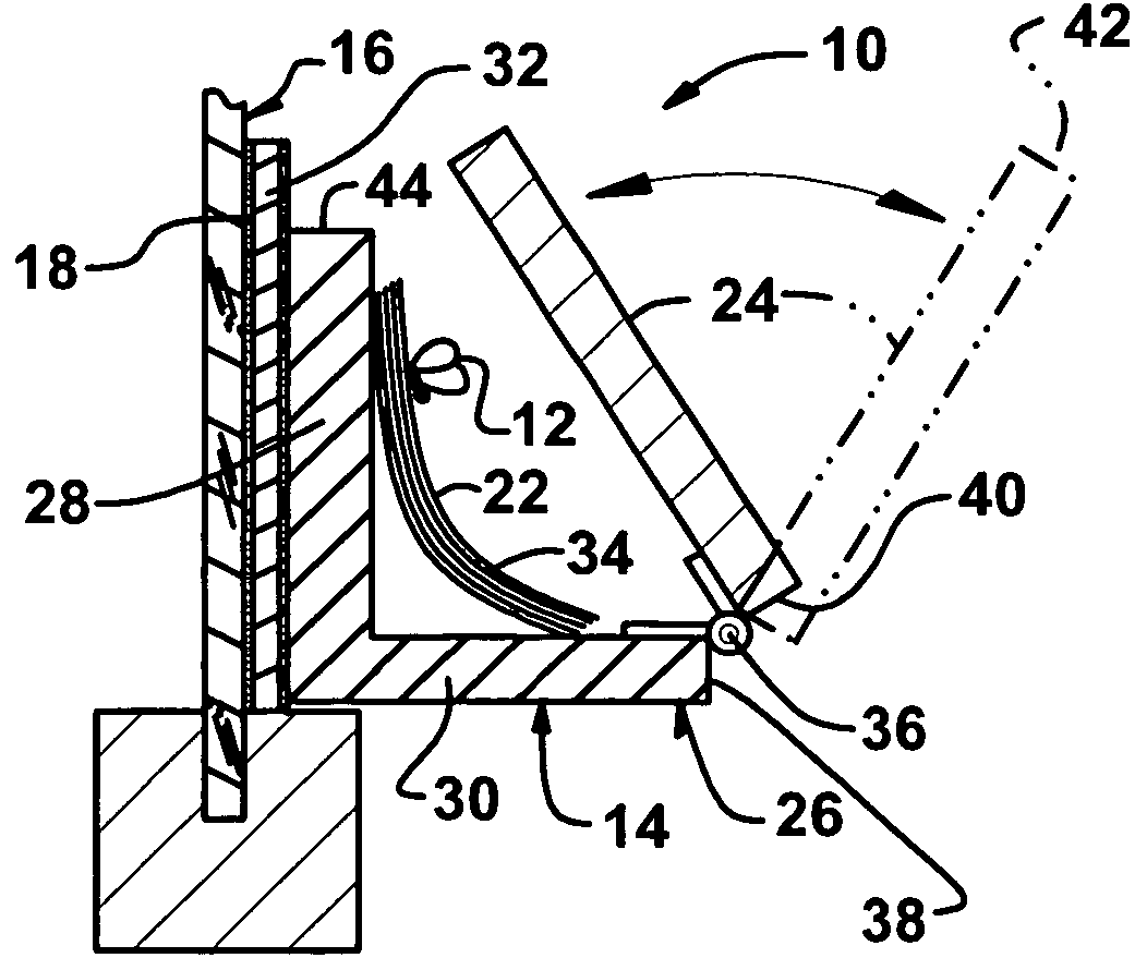
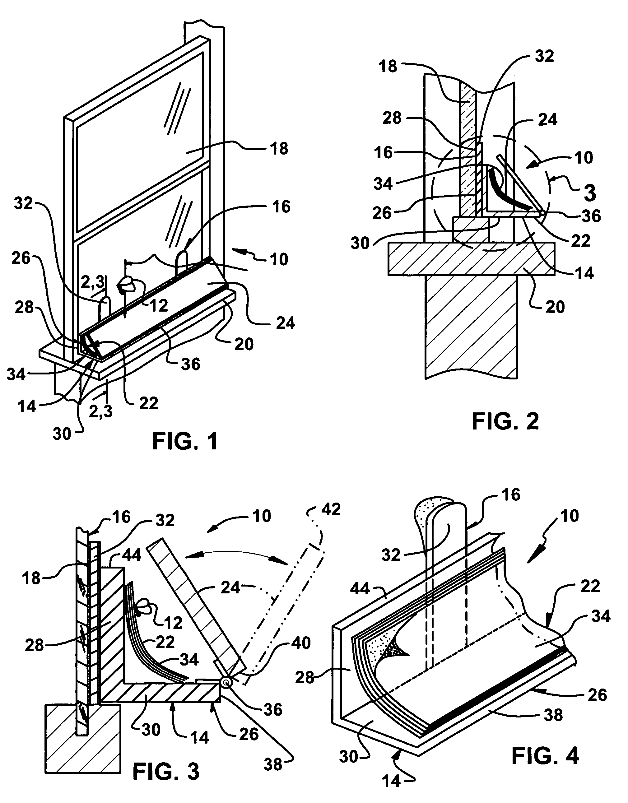
[0041]Referring now to the figures, in which like numerals indicate like parts, and particularly to FIGS. 1 through 4, which are a diagrammatic perspective view showing an embodiment of the present invention in use mounted horizontally to a window pane adjacent a window sill; a cross sectional view taken on line 2-2 of FIG. 1; an enlarged cross sectional view taken on line 3-3 of FIG. 1 and also of the area enclosed in the dotted circle indicated by arrow 3 in FIG. 2; and an enlarged diagrammatic perspective view of the present invention per se, with parts broken away, and as such, will be discussed with reference thereto.

[0042]The present invention is a device 10 for trapping flies 12 which comprises an elongated housing 14. A mechanism 16 is for mounting the housing 14 horizontally on an inside lower portion of a window pane 18 adjacent to a window sill 20. Another mechanism 22 for holding flies 12 is carried within the housing 14. The flies 14, when attracted to light coming thro...


PUM


Abstract

A device for trapping flies which comprises an elongated housing. A mechanism is for mounting the housing horizontally on an inside lower portion of a window pane adjacent to a window sill. Another mechanism for holding flies is carried within said housing. The flies, when attracted to light coming through the window pane, will hit the window pane and drop down to stick to the holding mechanism. A cover on the housing is to conceal the flies stuck to the holding mechanism.

Description

BACKGROUND OF THE INVENTION[0001]1. Field of the Invention[0002]The present invention relates to an insect catcher, and more particularly, a device for trapping flies.[0003]2. Description of the Prior Art[0004]Numerous innovations for flying insect traps have been provided in the prior art that will be described. Even though these innovations may be suitable for the specific individual purposes to which they address, however, they differ from the present invention.[0005]A FIRST EXAMPLE, U.S. Patent Office Document No. 560,040, Issued on May 12, 1896, to Maynadier teaches a fly catcher which comprises in combination with a partially darkened window, a sheet of glass or other transparent material treated with a sticky substance which is placed against a portion of the window through which light is admitted, and with the sticky side toward a room to which the window gives light, substantially as specified.[0006]A SECOND EXAMPLE, U.S. Patent Office Document No. 4,829,702, Issued on May ...

Claims


Application Information

Patent Timeline
IPC IPC(8): A01M1/24A01M1/14
CPCA01M1/145A01M1/24
Inventor WENNER, CARL F.
Owner WENNER CARL F
Learn More