
Digital amplifier system for driving a capacitive load

a digital amplifier and capacitive load technology, applied in the direction of pulse generators, pulse techniques, transmission, etc., can solve the problems of analog systems producing overshoot and ringing, further increasing costs, and increasing inefficiency, so as to reduce weight, volume and cost, and improve the slew rate. , the effect of improving the slew ra

Active Publication Date: 2010-06-29
NORTHROP GRUMMAN SYST CORP
View PDF25 Cites 19 Cited by
  • Summary
  • Abstract
  • Description
  • Claims
  • Application Information

AI Technical Summary

Benefits of technology

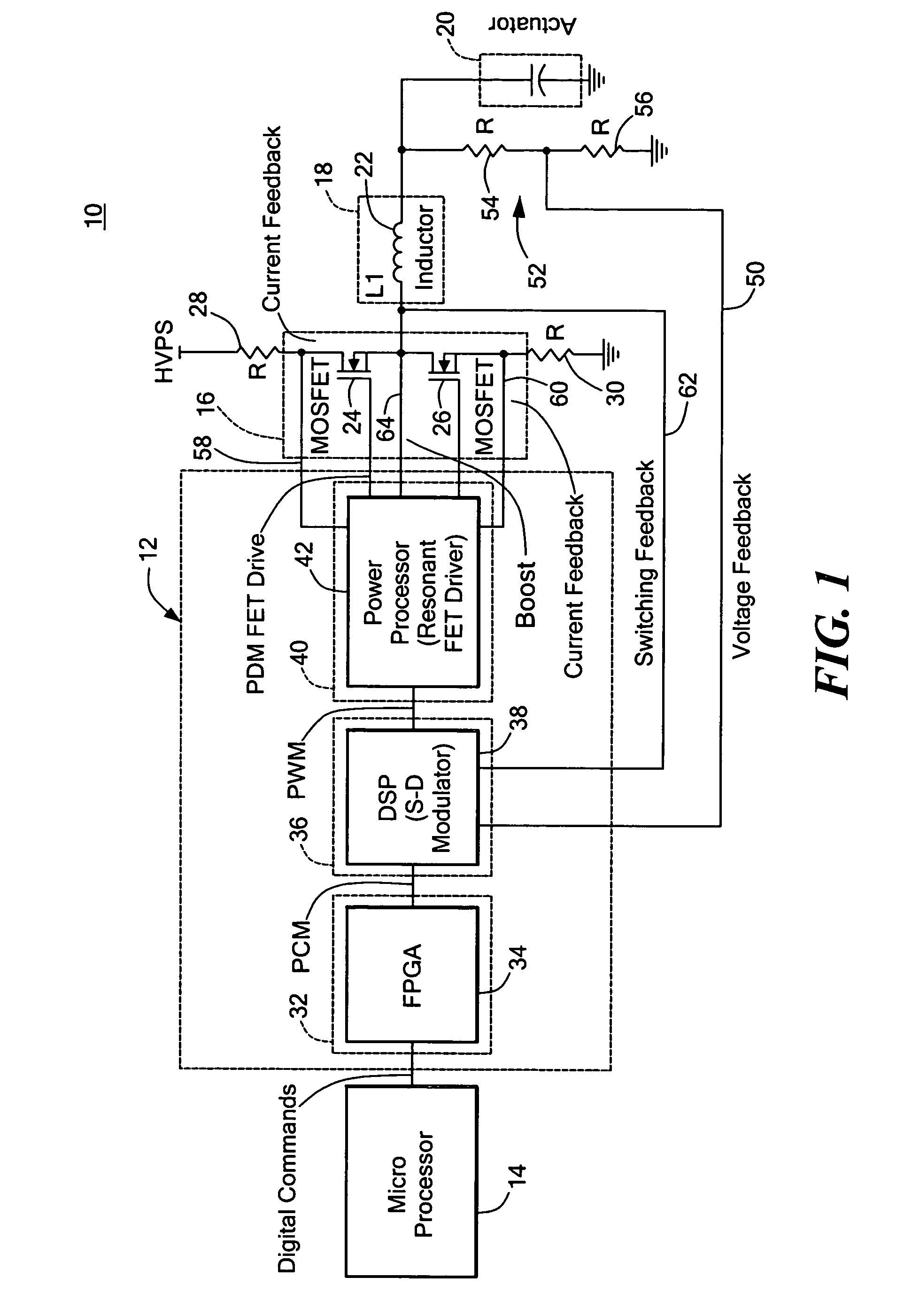
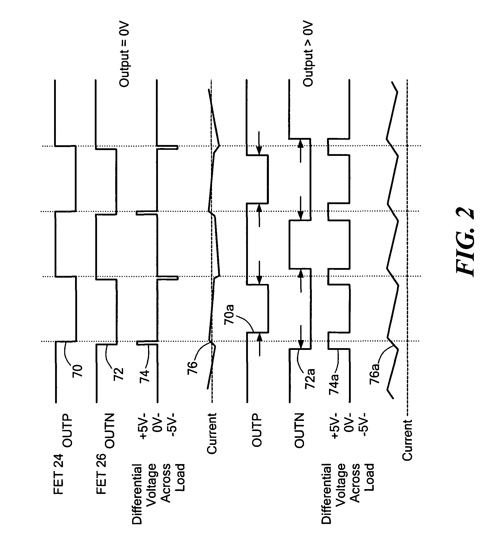
This patent describes a digital amplifier system for driving a capacitive load, which has higher efficiency, broader bandwidth, greater resolution, and lower weight, volume, and cost compared to analog systems. The system includes a digital amplifier controller that produces a pulse density modulation signal based on a digital input command, which is amplified by a switching amplifier and then demodulated by an inductive filter to provide a drive current to the capacitive load. The system has been found to have higher sampling rates, which allow for more precise control and reduce ringing and overshoot. The invention provides a more efficient and effective solution for driving capacitive loads.

Problems solved by technology

Further, large amounts of power require large heat sinks which mean heavier and larger packages which translates into overall larger and more robust packages to contain the additional weight and size, all of which further increases cost as well.
And all of this scaling and conversion introduces more inefficiency to the system.
Another disadvantage of the analog approach is that typically the best accuracy obtainable with the DAC and ADC are 16 bits which translates for a 100 volt supply to approximately 1.5 mv / lsb.
Analog systems also produce overshoot and ringing as a result of driving a reactive load with a voltage.
And the ringing can be at a frequency that is low enough for the actuator to physically respond yet high enough so that the amplifier cannot quickly correct.

Method used


Image

  • Digital amplifier system for driving a capacitive load
  • Digital amplifier system for driving a capacitive load
  • Digital amplifier system for driving a capacitive load

Examples


Embodiment Construction

[0024]Aside from the preferred embodiment or embodiments disclosed below, this invention is capable of other embodiments and of being practiced or being carried out in various ways. Thus, it is to be understood that the invention is not limited in its application to the details of construction and the arrangements of components set forth in the following description or illustrated in the drawings. If only one embodiment is described herein, the claims hereof are not to be limited to that embodiment. Moreover, the claims hereof are not to be read restrictively unless there is clear and convincing evidence manifesting a certain exclusion, restriction, or disclaimer.

[0025]There is shown in FIG. 1 a digital amplifier system 10 for driving a capacitive load including a digital amplifier controller 12 which is responsive to a digital input command from, for example, a microprocessor 14 to produce a pulse density modulation signal representative of that digital input command to a switching...


PUM


Abstract

A digital amplifier system for driving a capacitive load includes a digital amplifier controller responsive to a digital input command for producing a pulse density modulation signal representative of the digital input command; a switching amplifier for amplifying the pulse density modulation signal and an inductive filter for demodulating the amplified pulse density modulation signal to provide a drive current to drive a capacitive load in response to the digital input command.

Description

FIELD OF THE INVENTION[0001]This invention relates to a digital amplifier system for driving a capacitive load, and more particularly to such a digital amplifier system for driving a capacitive actuator for a deformable mirror.BACKGROUND OF THE INVENTION[0002]Typically the high voltage driver systems in use to drive capacitive actuators for deformable mirrors are based on analog technology. A microprocessor delivers a digital input command to a digital to analog converter (DAC) which drives an amplifier to supply drive current to the capacitive actuator. The amplifier typically has a totem pole output stage using bipolar transistors. To keep control over the output stage a bias current must be maintained. With even a small bias current at the 100 volts required by the actuator the power drain is considerable e.g., 2 watts. Considering that many deformable mirrors require 1000 channels (actuators) or more the power loss e.g. 2000 w can build up quickly. Add to this that analog amplif...

Claims


Application Information

Patent Timeline
Patent Type & Authority Patents(United States)
IPC IPC(8): H04B14/04
CPCH03F3/217
Inventor BONFIGLIO, JOSEPH WILLIAM
Owner NORTHROP GRUMMAN SYST CORP
Learn More