
Hot-air fabric welder for waterproofing tape

a fabric welder and fabric welder technology, which is applied in the direction of manufacturing tools, soldering devices, auxillary welding devices, etc., can solve the problems of high product rejection rate, inability to use a conventional tape welder, and enormous cost, so as to improve productivity and improve welding quality , excellent water tight

Active Publication Date: 2010-06-29
SEO GI WON
View PDF5 Cites 4 Cited by
  • Summary
  • Abstract
  • Description
  • Claims
  • Application Information

AI Technical Summary

Benefits of technology

Enables the production of waterproof products with excellent watertight seals and improved productivity by allowing for seamless, curved welds on complex shapes, reducing rejection rates and production costs by using a single machine for diverse seam types.

Problems solved by technology

But because it is not possible for a conventional tape welder to utilize a wide or narrow support roller depending on the width of the synthetic resin tape, it has been used as it is.
Because of that, using a tape welder of one kind regardless of the width of the synthetic resin has many problems such as a high rejection rate of the product or an enormous cost if different tape welders are provided according to the width of the synthetic resin tape.
However, since the conventional hot-air fabric welder for waterproofing tape has flat upper roller and lower roller units, it is possible to heat-weld only a straight seam with a waterproof tape.
Therefore, various constraints limit the process of heat-welding the waterproof tape to a seam having various curve shapes such as a neck portion, shoulder, chest and sleeve, when using a conventional hot air welder.
In order to produce products made of waterproof sheet of synthetic resin with curved surfaces such as a tent, raincoat, jumper, hat or ski suit, the worker makes the product by putting it in by force and rotating it along the relevant curvature by force, so creases occur in the welding portion of the waterproof tape due to overlapping of the product fabric or the waterproof tape, which causes the appearance to be not beautiful and lowers the marketability of the product.

Method used


Image

  • Hot-air fabric welder for waterproofing tape
  • Hot-air fabric welder for waterproofing tape
  • Hot-air fabric welder for waterproofing tape

Examples


first embodiment

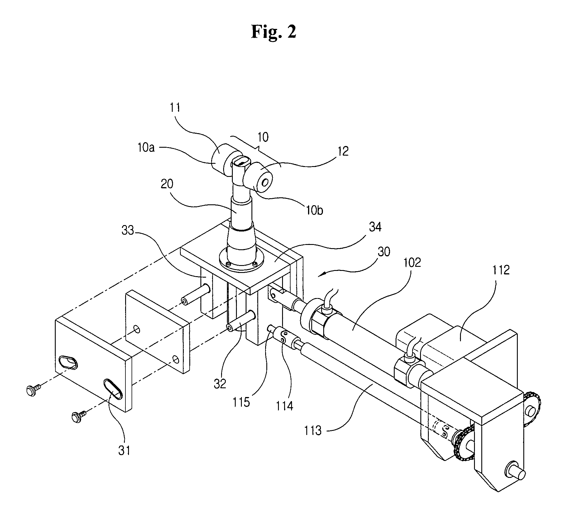
[0034]FIG. 2 is a perspective view showing the lower roller unit and the drive unit of a waterproof tape hot-air fabric welder according to a first embodiment of the present invention, and FIG. 3 is a sectional view showing the assembly of the lower roller and the drive unit illustrated in FIG. 2.

[0035]In the present embodiment, the lower roller unit 10 is formed by dividing it into a flat roller body 11 and a tapered roller body 12, respectively, and these are joined to both sides of the upper end of the support 20. When the flat roller portion 10a of the flat roller body 11 rotates in correspondence to the upper roller 111, the rotation velocity of both ends is uniform, so it plays a role of moving the object of waterproof work in a straight line.

[0036]When the tapered roller portion 10b of the tapered roller body 12 rotates in correspondence to the upper roller 111, the rotation velocity of both ends are different from each other, so the object of waterproof work moves in an arc ...

second embodiment

[0050]FIG. 6 is an exploded perspective view showing the lower roller unit and the drive unit of a waterproof tape hot-air fabric welder according to a second embodiment of the present invention, and FIG. 7 is a perspective view showing the lower roller unit and the drive unit of the waterproof tape hot-air fabric welder according to the second embodiment of the present invention.

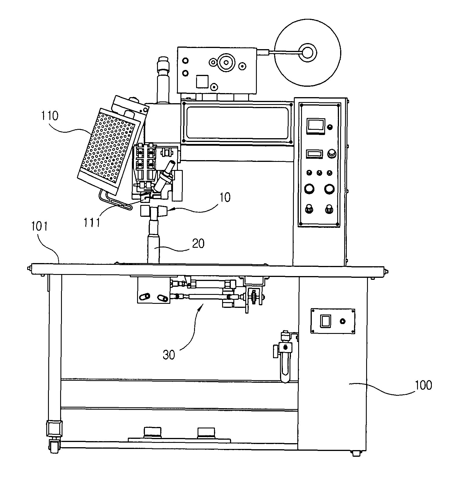
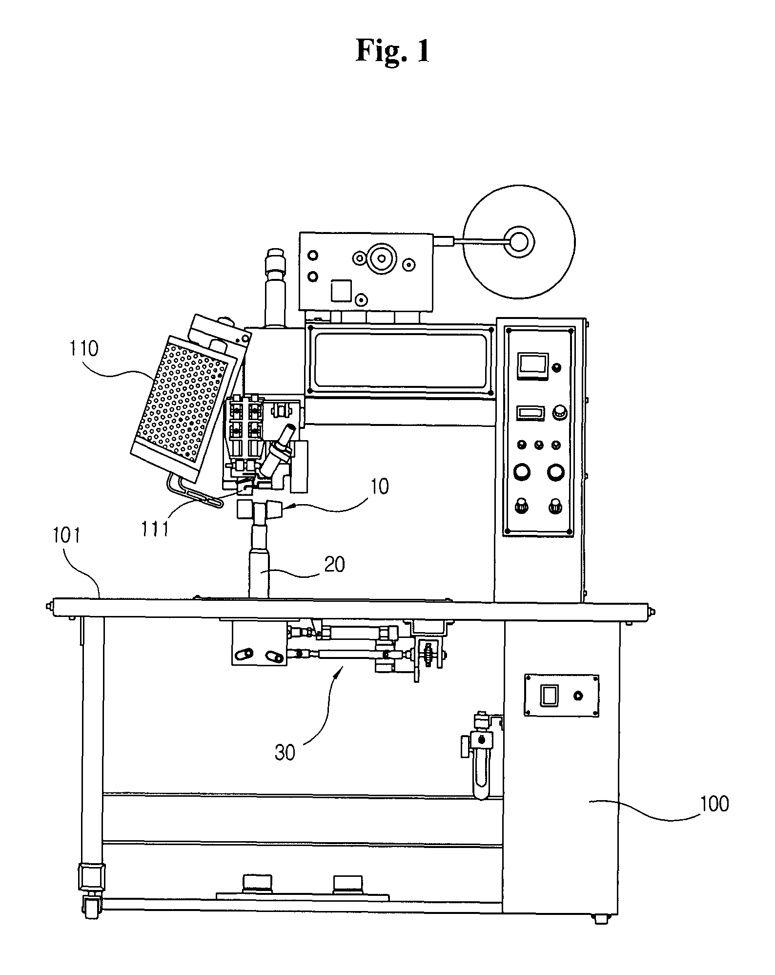
[0051]As mentioned above with FIG. 1, the hot-air fabric welder for waterproofing tape of the present invention is provided with a hot-air generating means 110 and an upper roller 111 facing downward on the work table 101 of the main body 100. Below the upper roller 111 are arranged a flat roller body 11 having a flat roller portion 10a and a tapered roller body 12 having a tapered roller portion 10b separated by first and second supports 20a, 20b protruding above the work table 101.

[0052]At this time, the flat roller body 11 and tapered roller body 12 are rotatably fitted at the upper ends of the first sup...

third embodiment

[0063]FIG. 12 is an exploded perspective view showing a hot-air fabric welder for waterproof tape according to a third embodiment of the present invention, and FIG. 13 is a sectional view showing the lower roller unit and the drive unit of the waterproof tape hot-air fabric welder according to the third embodiment of the present invention.

[0064]As shown in the drawings, both ends of the lower roller unit 10 according to the present embodiment are hinged on the roller support 20. The whole shape of the lower roller unit 10 is a cylindrical ellipsoid configuration. In the central portion of the lower roller unit 10 is formed a straight cylindrical portion 10a oriented horizontally, and on both sides of the straight portion 10a are formed tapered roller portions 10b, 10b with the center point C identical.

[0065]At this time, the lower roller unit 10 mounted on the roller support 20 is rotated by power transmitted from the drive motor 112 underneath the work table 101 of the main body 10...


PUM

PropertyMeasurementUnit
circumferenceaaaaaaaaaa
shapeaaaaaaaaaa
torqueaaaaaaaaaa

Abstract

A hot-air fabric welder for waterproofing tape is invented for selectively welding straight portions and arc portions. The hot-air fabric welder for waterproof tape is comprised of: a lower roller unit including a flat roller portion and a tapered roller portion mounted to the upper end of a support. The lower roller unit is divided into a flat roller body and a tapered roller body for selectively positioning into contact with the upper roller, so that the surface of the lower roller unit contacts the upper roller. A driving means is provided for rotating the lower roller unit. A pivoting means is provided for rotating the support on which the lower roller unit is mounted for selective use of the flat roller portion or the tapered roller portion. A hot-air generating unit is linked to the lower roller unit, driving unit and pivoting unit, and an upper roller is arranged above the lower roller unit.

Description

BACKGROUND OF THE INVENTION[0001]1. Field of the Invention[0002]The present invention relates to a hot-air fabric welder for waterproofing tape which completely waterproofs a seam portion by heat-welding a synthetic resin tape on the seam portion of a product made of a waterproof sheet such as a tent, raincoat, jumper, hat or ski suit, and more specifically to a hot-air fabric welder for waterproofing tape for manufacturing both a straight-line heat-welded portion and an arc-shaped heat-welded portion through selective use of a flat roller portion or a tapered roller portion in opposition to the upper roller, by configuring the appropriate part of the lower roller unit in opposition to the upper roller.[0003]2. Related Prior Art[0004]In general, for products that need waterproofing such as a tent, raincoat, jumper, hat or ski suit, complete waterproofing is possible for the waterproof sheet, but pinholes are perforated along the seam in the process of sewing it. Therefore, for water...

Claims


Application Information

Patent Timeline
Patent Type & Authority Patents(United States)
IPC IPC(8): B32B37/00
CPCB23K37/04B29C66/20B29C66/4722B29C66/8167B29C66/822B29C66/83413D05B1/26B29C65/10B29C65/00Y10T156/1741B29C66/2442B29C66/8324B29K2995/0069B29L2007/007B29L2031/4814B29L2031/4842B29L2031/485B29L2031/52B29C66/729B29C66/1122B29C66/244B29C66/81415B29C66/81419B29C66/845
Inventor SEO, GI-WON
Owner SEO GI WON
Learn More