
Variants in graphical modeling environments

a modeling environment and variable technology, applied in the field ofgraphical modeling environments, can solve the problems of reducing syntactic clarity and usability of block diagrams, unable to use cascades, and no way,

Active Publication Date: 2010-06-22
THE MATHWORKS INC
View PDF10 Cites 28 Cited by
  • Summary
  • Abstract
  • Description
  • Claims
  • Application Information

AI Technical Summary

Benefits of technology

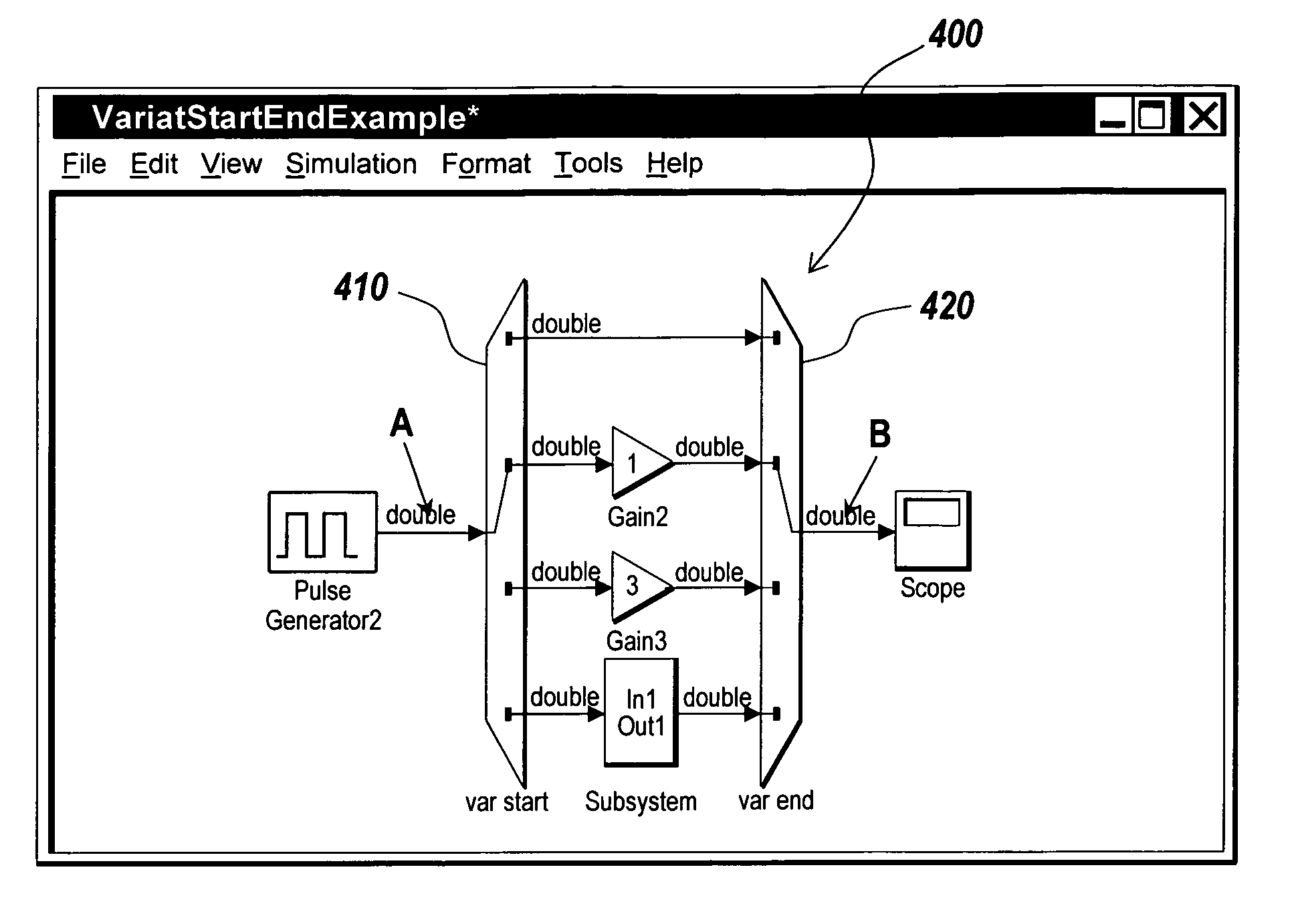
[0015]There is a need for graphical modeling environments that provide mechanisms for enabling an individual element (a component or a module) within a graphical model to have multiple implementations that may be swapped in and out by a system designer. The present invention provides such graphical modeling environments that enable the system designer to perceive all possible implementations for the component or module in the graphical model. The present invention also enables the system designer to select one of the implementations for the component or module to build the required specification of the graphical model. The present invention may be useful in the design of any type of graphical model that allows engineers to maintain a single overall model for the entire class of systems they are currently designing. The present invention also enables this model to be configured on demand to exercise specific implementations.

Problems solved by technology

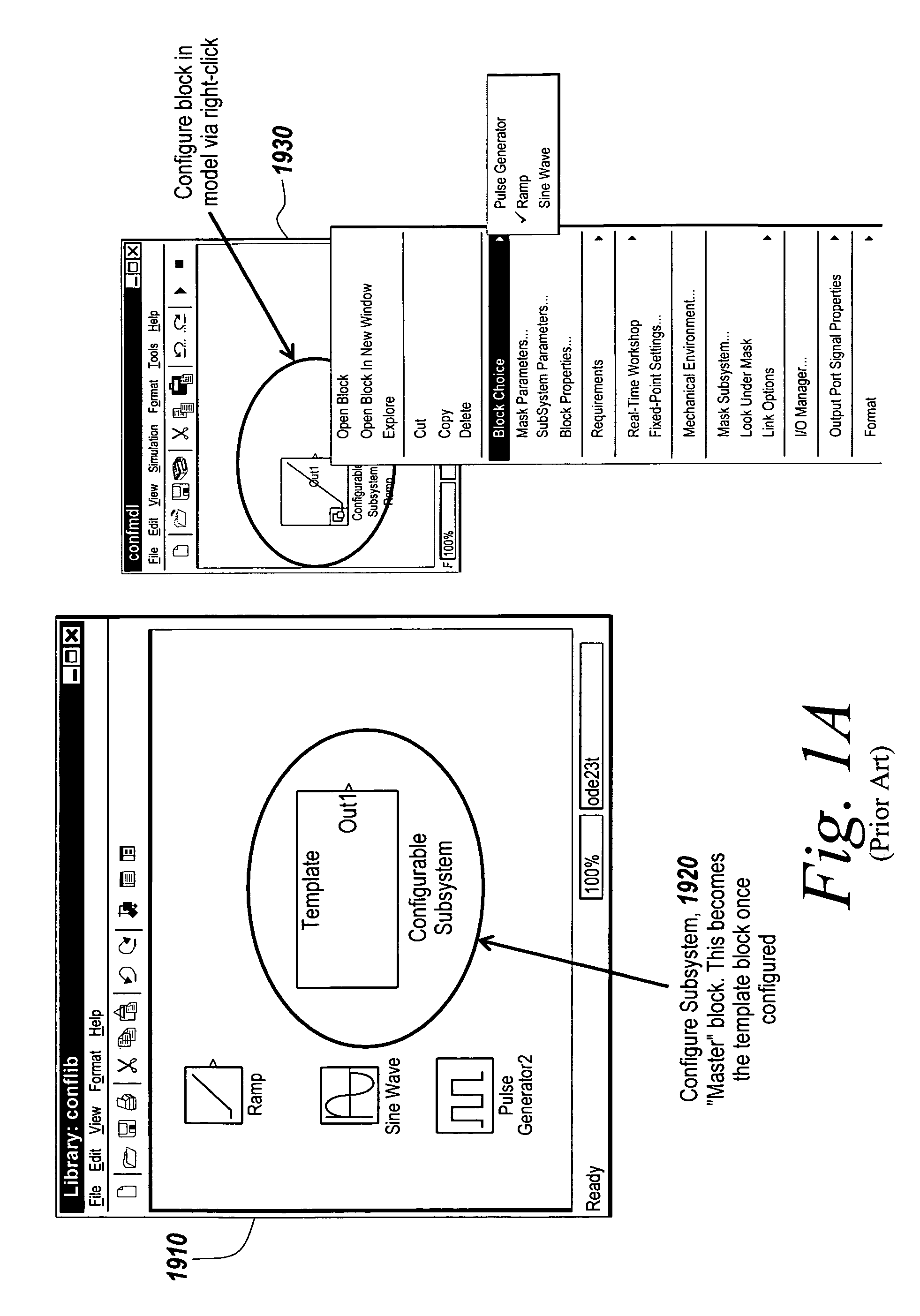
1. The configurable subsystem must reside within a library and cannot be placed directly within a model. Thus, there is no way to directly specify a different configuration for a model, only indirectly via libraries.
2. There is reduced syntactic clarity and usability in the block diagrams because users cannot see all of the available configurations in the host model.
3. Users are offered no mechanism for saving away the active configurations. They are constrained to always bundling the model with the library containing all configurable subsystems.
4. Model builders are constrained to using subsystems to represent their model configurations. Hence they do not have the flexibility of using cascades of blocks for each configuration. Such cascades may sometimes be desirable in order to shed more light on the system that is being modeled.
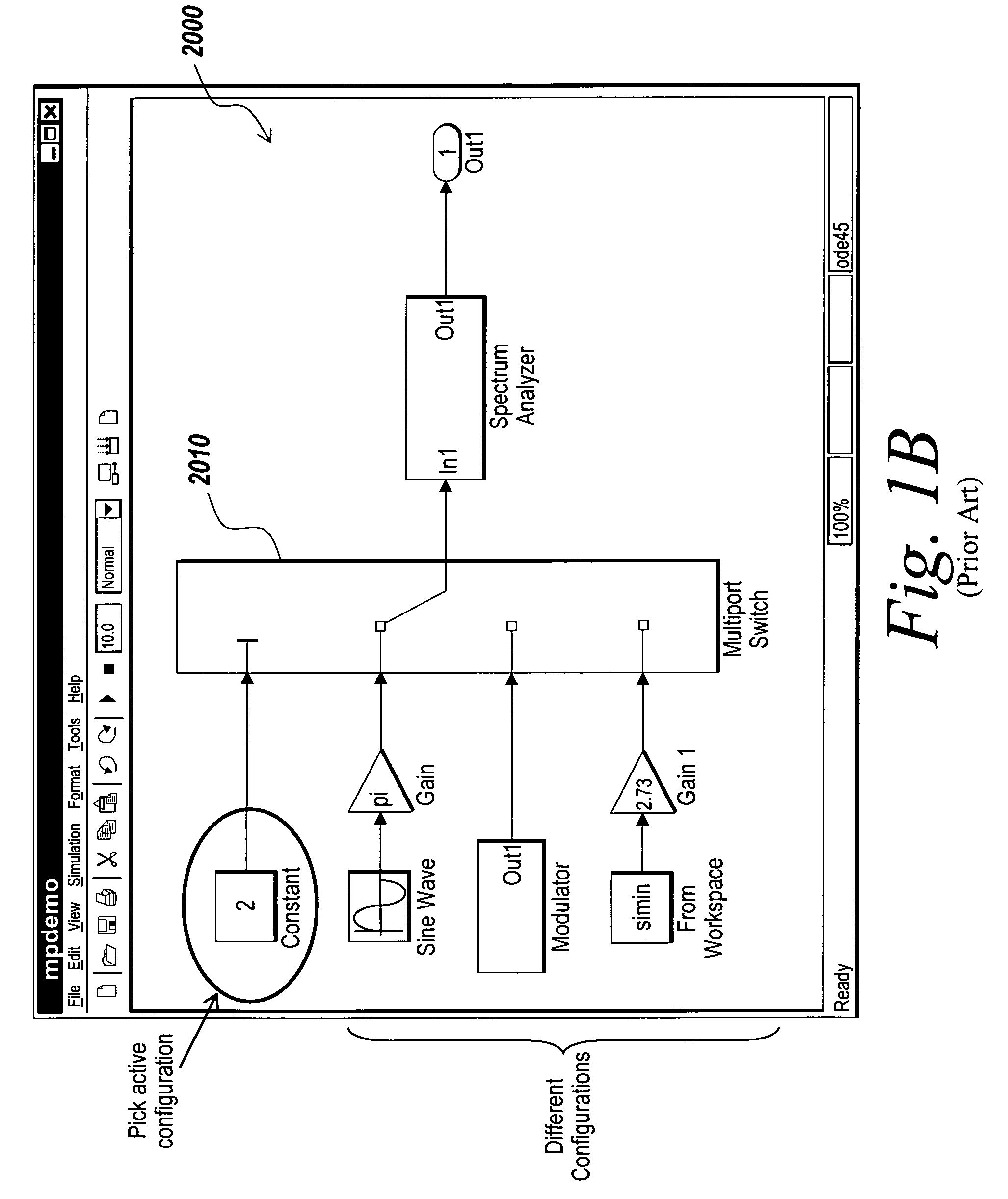
1. To allow for run-time switching between modes, all the blocks in the input branches of a switch are generally included in the compiled and linked versions of the model. This adds a significant performance overhead at the time of block diagram execution. While attempts have been made to optimize away inactive branches of the Switch at the time of execution, these attempts need complex analysis, are not always successful, and still require all of the configurations to be in memory simultaneously.
2. Users can not save away only the active configuration.

Method used


Image

  • Variants in graphical modeling environments
  • Variants in graphical modeling environments
  • Variants in graphical modeling environments

Examples


Embodiment Construction

[0046]Certain embodiments of the present invention are described below. It is, however, expressly noted that the present invention is not limited to these embodiments, but rather the intention is that additions and modifications to what is expressly described herein also are included within the scope of the invention. Moreover, it is to be understood that the features of the various embodiments described herein are not mutually exclusive and can exist in various combinations and permutations, even if such combinations or permutations are not made express herein, without departing from the spirit and scope of the invention.

[0047]The illustrative embodiment of the present invention provides a graphical modeling environment in which a graphical model is generated and simulated / executed. In the description of the illustrative embodiment, the simulation of the model is also referred to as the execution of the model. The illustrative embodiment will be described solely for illustrative pu...


PUM


Abstract

This invention allows users to build, manipulate, and finally deploy various model configurations with little performance overhead, better syntactic clarity and configuration flexibility.

Description

RELATED APPLICATIONS[0001]The present application claims priority to a U.S. provisional application, Patent Application No. 60 / 580,212, filed Jun. 15, 2004, the contents of which are incorporated herein by reference.FIELD OF THE INVENTION[0002]The present invention relates to graphical modeling environments, in particular to methods, systems and computer program products for providing variants in the graphical modeling environments.BACKGROUND OF THE INVENTION[0003]Various classes of block diagrams describe computations that can be performed on application-specific computing hardware, such as a computer, microcontroller, FPGA, and custom hardware. Classes of such block diagrams may include time-based block diagrams such as those found within Simulink® from The MathWorks, Inc. of Natick, Mass., state-based and flow diagrams such as those found within Stateflow® from The MathWorks, Inc. of Natick, Mass., and data-flow diagrams. A common characteristic among these various forms of block...

Claims


Application Information

Patent Timeline
Patent Type & Authority Patents(United States)
IPC IPC(8): G06G7/48G06F9/45G06F17/50
CPCG06F17/5009Y02T10/82G06F2217/04G06F30/20G06F2111/02
Inventor CIOLFI, JOHNGUO, YANGMANI, RAMAMURTHY
Owner THE MATHWORKS INC
Learn More