[0006]Several features of the base unit 112 are beneficially adapted to enhance the use of the storage container 100 in a medical environment. First, the container base 114 is preferably sized with an area of less than approximately 2 square feet, and more specifically with a width of 12 inches or less between the sidewalls118, and with a depth of 24 inches or less in the transverse direction. This ensures that the container base 114 is relatively compact and can relatively easily fit atop a portion of a medical service
cart (e.g., a nurse's or anesthesiologist's
cart) while leaving space atop the cart for medical files,
medical instruments, or other matter. The somewhat elongated shape of the container base 114, as opposed to a square base or the like, makes more efficient use of cart space by allowing the storage container 100 to extend along the edge of a cart's platform without extending overmuch into the central area of the platform. (Medical personnel often find it convenient to leave a central area of the cart platform free to accommodate tools for addressing whatever tasks are at hand, or to accommodate an open file so that the central area of the platform effectively serves as a mobile desktop for writing purposes, etc.)
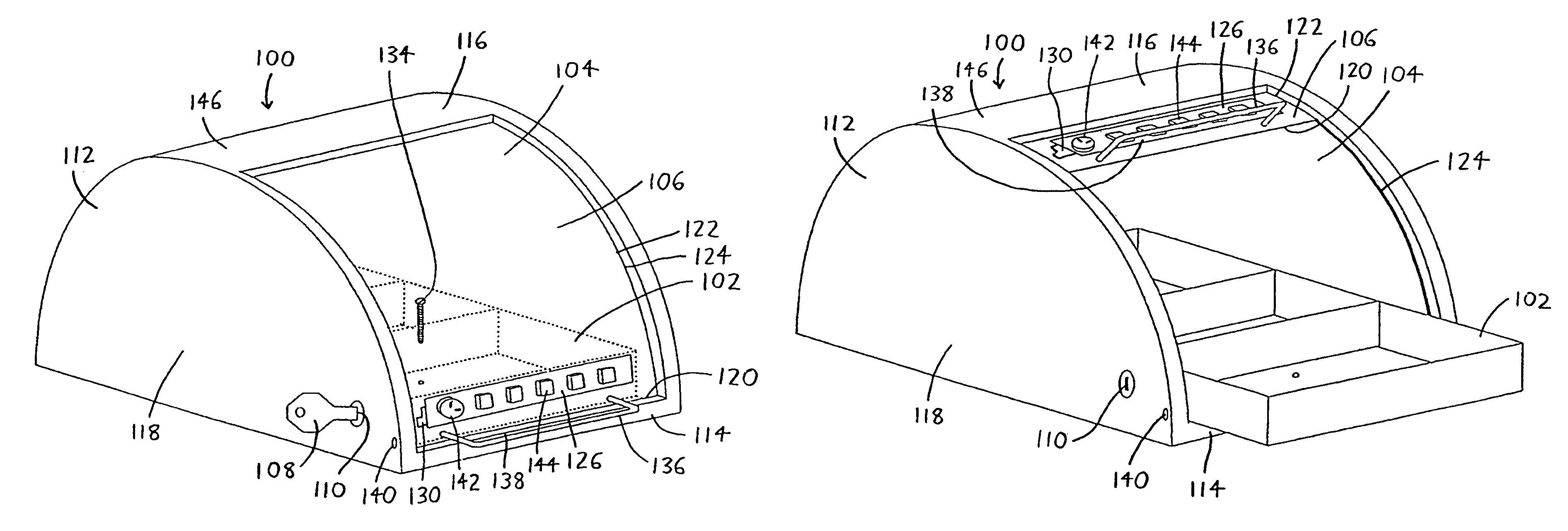
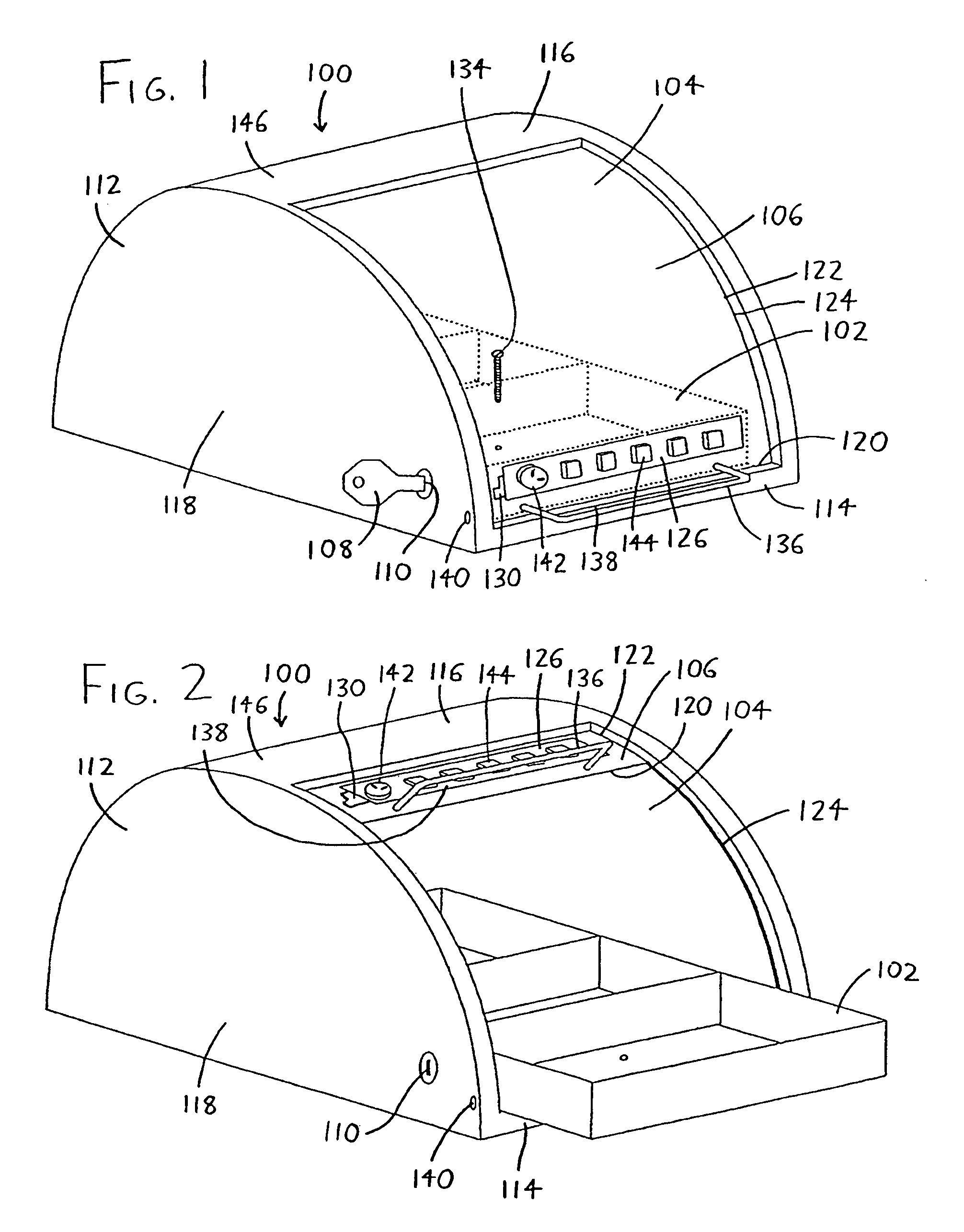
[0007]Second, at least a major portion of the container top 116 is sloped such that the container top 116 cannot stably support an object having a flat base atop the container top 116 (i.e., the container top 116 is sloped such that when the storage unit is placed on a medical cart, objects such as files, when placed atop the storage container 100, will slide off, particularly when the cart starts or stops motion). This serves to deter users from stacking files or other matter atop the storage container 100, which is preferably left as visible and as free from obstruction as possible so that medicines stored therein can better be readily accessed when needed.
[0008]The container door 106 is then preferably formed of a single piece of at least substantially transparent rigid material, or is otherwise windowed so that it is at least substantially transparent over at least a major portion of its area. The container door 106 has opposing upper and lower edges (the lower edge 120 being particularly visible in FIG. 2), and opposing arcuately curved side edges 122 which extend between the upper and lower edges, and which are slidably engaged within grooves 124 defined in the container sidewalls 118. The container door 106 may slide in the grooves 124 between an open position (as in FIG. 2), wherein an opening is defined between the container door 106 and the base unit 112 to allow access to the container interior 104, and a closed position (as in FIGS. 1 and 3), wherein the container door 106 and the base unit 112 enclose the container interior 104. As can be seen in the drawings, the container door 106 presents a curved surface to the user which will not support the placement of objects thereon, and which also provides both a frontal and a top view of the medicines stored within the container 100, which is useful if personnel need to make a rapid
visual assessment of the medicines therein. In contrast, a container door having a corner defined therein will tend to introduce an obstacle or
distortion into the user's view, even if such corner is formed of transparent material. Additionally, the curvature of the container door 106 is preferably slightly different from the curvature of the grooves 124, whereby some degree of friction exists between the container door 106 and the base unit 112 (particularly when formed of plastic) so that the container door 106 will generally remain in the position to which it is opened without falling shut, and at the same time it will easily open and close.
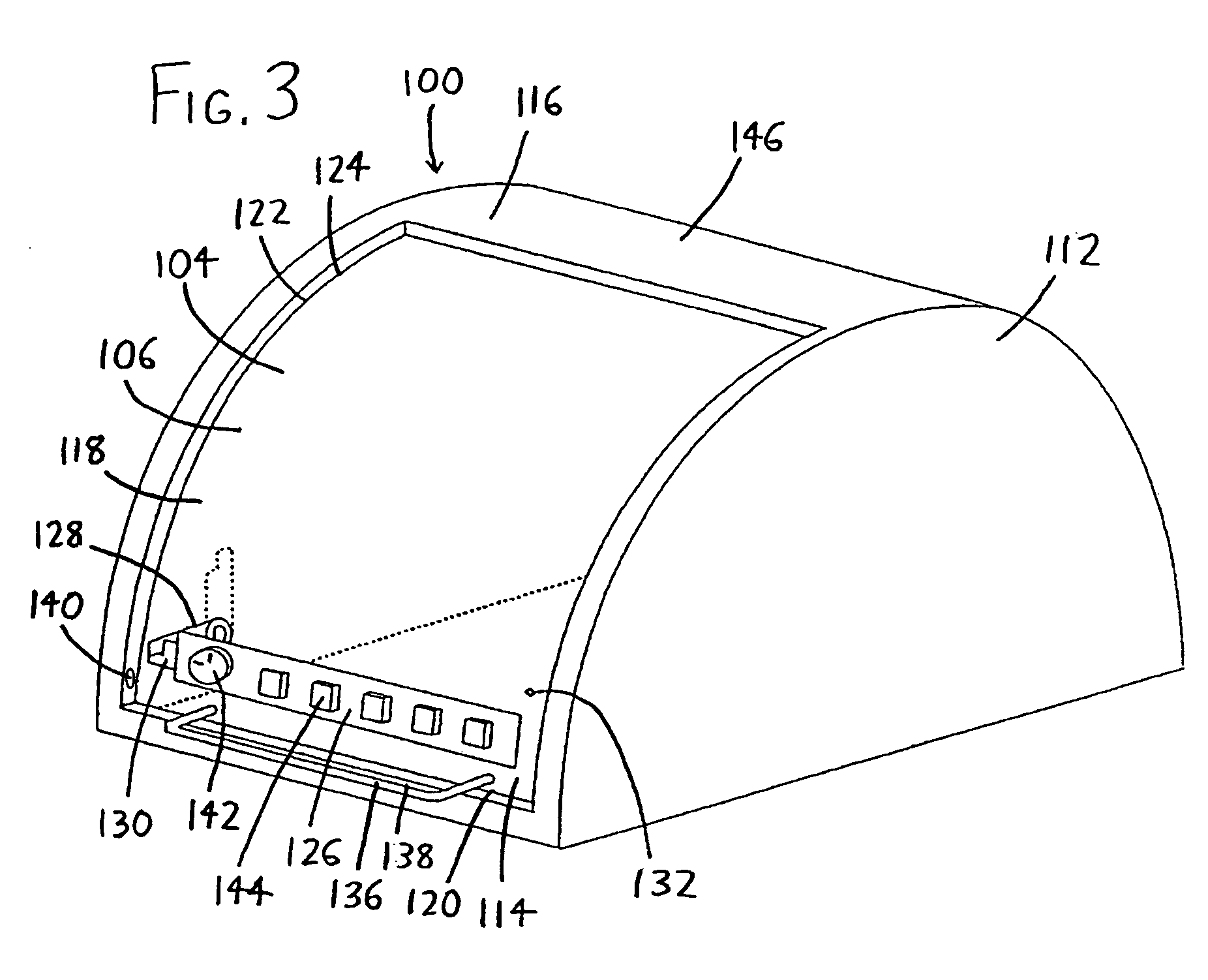
[0009]The container door 106 is preferably latchable and lockable in its closed position so that medicines may be secured against theft or loss. Most preferably, the storage unit includes a latch which is engageable between the container door106 and the base unit 112, and wherein the latch has at least two separate
modes of engagement and disengagement, such as by a key 108 insertable into one of the container door 106 and the base unit 112 for engaging and disengaging the latch, and also by a keyless entry means (e.g., a
touchpad combination lock 126) for engaging and disengaging the latch without a key 108. This allows different
modes of entry by different personnel, e.g., a
pharmacist having a
master key 108 may restock a group of storage containers, and the storage containers may then be distributed to nurses or other personnel, with each storage container 100 being openable by entering a combination (unique to the container 100 and to its user) on its keypad 126. The dual locking scheme is easily and inexpensively implemented in the manner best illustrated in FIG. 3, wherein a first latch 128—shown as a rotating bar actuated by the key 108 of FIG. 1, and which is spaced from the sidewall 118—rotates between a disengaged position (shown in phantom / dashed lines) spaced from the container base 114 and an engaged position closer to the container base 114. A second latch 130 extends from the keyless entry means (i.e., the keypad), and it may be situated in an engaged position wherein it extends closely adjacent to the sidewall 118, or in a disengaged position wherein it is withdrawn to a position closer to the keyless entry means. Thus, if the first (keyed) latch 128 is put in its engaged position with the container door 106 closed, and the second (keyless) latch 130 is then put in its engaged position, the second latch 130 interferes with the first latch 128 if one attempts to open the container door 106, and the container door 106 is effectively locked shut. At the same time, unlocking of the first latch 128 (i.e., using the key 108 to rotate it out of the path of the second latch 130), or unlocking the second latch 130 (i.e., actuating the keypad 126 to translate the second latch 130 so that it does not encounter the first latch 128 as the container door 106 is opened), will allow the container door 106 to be opened. In short, the first and second latches 128 and 130, when both in their engaged positions, engage the container door 106 to the base unit 112 when the container door 106 is in its closed position. On the other hand, when at least one of the first and second latches 128 and 130 is in its disengaged position, the container door 106 is slidable between its open and closed positions.
[0010]The storage container 100 is also preferably provided with a medication tray 102 (shown in FIGS. 1 and 2) which is insertable and removable within the container interior 104, and which is sized to fit on the container base 114 within the container interior 104 when the container door 106 is closed. Additionally, the medication tray 102 is preferably removably affixable to the container base 114 from within the container interior 104 (and not from the container exterior), as by providing one or more securement apertures 132 (see FIG. 3) within the container base 114 and then providing attachment means 134 (see FIG. 1) for extending into and engaging the securement apertures 132 within the container base 114. As illustrated by FIG. 1, this could be done by simply inserting a
fastener 134 through the medication tray 102 and into a securement aperture 132 (visible only in FIG. 3) in the container base 114. The attachment means could alternatively take more complex forms such as a latch which pivots from the medication tray 102 into the securement aperture 132, a pin which engages the medication tray 102 to the container base 114 when inserted through the medication tray 102 and into the securement aperture 132 and then being rotated, or other forms as discussed elsewhere in this document. This feature allows personnel (e.g.,
pharmacy staff or medication control officers) to insert a stocked medication tray 102 into the container 100 and
affix it therein in a manner whereby the medication tray 102 cannot be easily disengaged by one who only has access to the exterior of the storage container 100. More preferably, the attachment means extends through the medication tray 102, through any securement aperture(s) 132 in the container base 114, and then engages any service cart or other structure atop which the storage container 100 is situated. Thus, personnel may both secure the medication tray 102 within the storage container 100 and also secure the storage container 100 to a service cart or other structure at the same time, thereby better ensuring that both the medication tray 102 and the storage container 100 are not easily removed.
