Optical connector having a fitting protrusion or fitting recess used for positioning
a technology of optical connectors and insertion holes, which is applied in the field of optical connectors having a fitting protrusion or a fitting recess used for positioning, can solve the problems of increasing the number affecting the positioning accuracy affecting the quality of optical fiber insertion holes, etc., to achieve good positioning accuracy, easy to increase the number of cores, and low manufacturing cost
- Summary
- Abstract
- Description
- Claims
- Application Information
AI Technical Summary
Benefits of technology
Problems solved by technology
Method used
Image
Examples
first embodiment
[0035]A first embodiment of the present invention will be described with reference to FIG. 2. An optical connector 10 of this embodiment is a multi-core optical connector of a fitting pin positioning type which is integrally formed of resin. As shown in FIG. 2, multiple optical fiber insertion holes 12 arranged in a lateral line are opened on a connection end surface 11a of a ferrule body 11 which serves as a connection surface with an opponent optical connector (not shown). Two fitting holes 13 for positioning are formed above and below these optical fiber insertion holes 12 so as to sandwich the row of the optical fiber insertion holes 12 therebetween. A diameter of each fitting hole 13 is larger than those of the optical fiber insertion holes 12. A straight line L is a straight line that horizontally passes through the center of the connection end surface 11a. The center of each of the optical fiber insertion holes 12 is located on the straight line L. The two fitting holes 13 ar...
second embodiment
[0049]A second embodiment of the present invention will be described with reference to FIG. 3. In FIG. 3, constituents that are common to those in FIG. 2 will be designated by the same reference numerals.
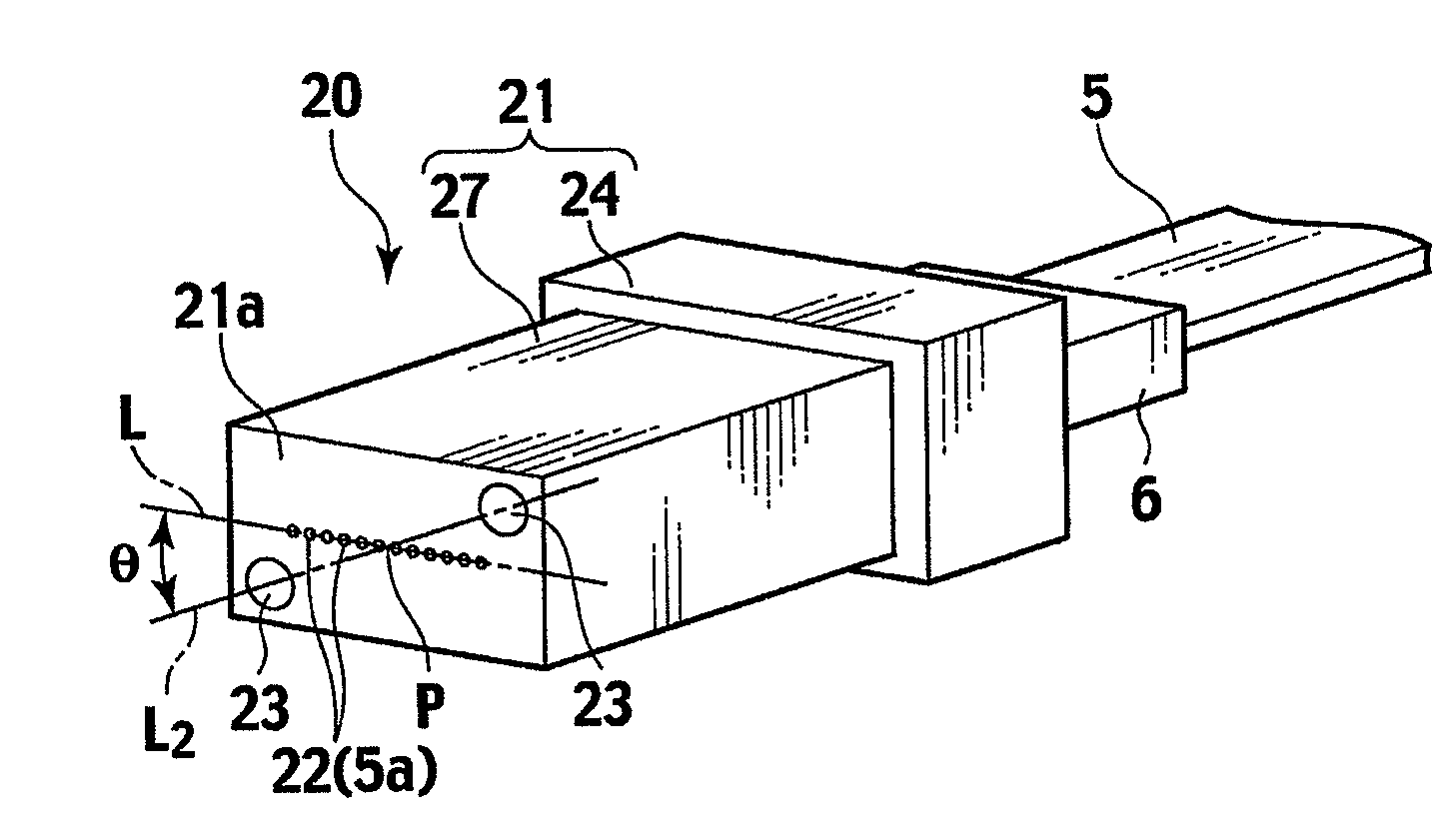
[0050]As shown in FIG. 3, an optical connector 20 according to the second embodiment is an optical connector similar to the first embodiment. Multiple optical fiber insertion holes 22 arranged in one lateral row and two fitting holes 23 having a larger diameter than that of the optical fiber insertion holes 22 are formed on a connection end surface 21a of a ferrule body 21. The two fitting holes 23 for positioning are formed on mutually vertically opposite sides relative to a straight line L and near corners of the connection end surface 21a. These two fitting holes 23 are formed in positions that are point-symmetrical with respect to a center P of the row. Moreover, the centers of the two fitting holes 23 are located on a straight line L2 that defines a predetermined angle θ other ...
third embodiment
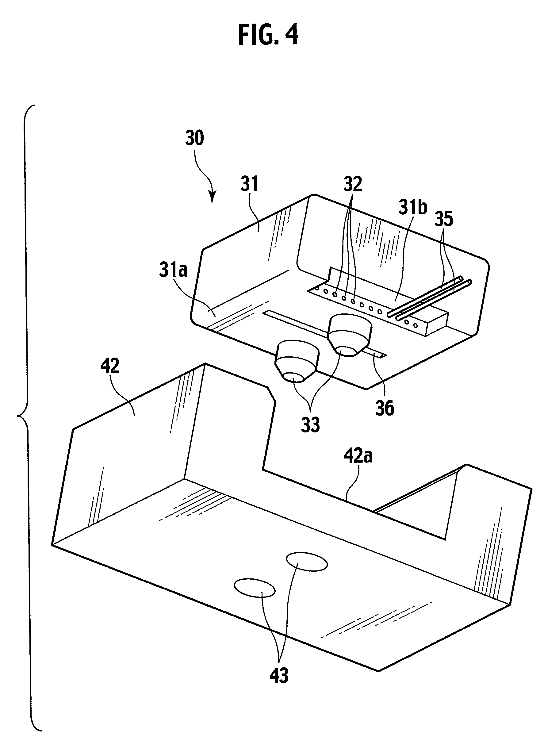
[0053]A third embodiment of the present invention will be described with reference to FIG. 4 to FIG. 7. An optical connector 30 according to the third embodiment is an optical connector of an optical path change type. An optical connector 30 according to the third embodiment includes a reflector provided on a ferrule body 31. In FIG. 4, a recess 36 functioning as the reflector is formed as an example. The reflector couples optical axes of light propagated through multiple optical fibers 35 fitted to the ferrule body 31 and arranged side by side in one row (in the vertical direction of FIG. 5) at constant intervals, with optical axes of multiple optical elements 41 provided laterally in one row (in the vertical direction of FIG. 5) with constant intervals on a fitting surface 42a of a positioning table 42 on which the ferrule body 31 is mounted. Specifically, the reflector reflects the light so as to guide the light from the optical elements 41 to the optical fibers 35 or to guide th...
PUM
 Abstract
Description
Claims
Application Information
 - R&D
- Intellectual Property
- Life Sciences
- Materials
- Tech Scout
- Unparalleled Data Quality
- Higher Quality Content
- 60% Fewer Hallucinations
Browse by: Latest US Patents, China's latest patents, Technical Efficacy Thesaurus, Application Domain, Technology Topic, Popular Technical Reports.
© 2025 PatSnap. All rights reserved.Legal|Privacy policy|Modern Slavery Act Transparency Statement|Sitemap|About US| Contact US: help@patsnap.com


