Eureka AIR delivers breakthrough ideas for toughest innovation challenges, trusted by R&D personnel around the world.

Liquid dispenser

a liquid dispenser and dispenser technology, applied in the direction of liquid transfer devices, instruments, single-unit apparatuses, etc., can solve the problems of liquid dispensers not being able to be freestanding on the bottom end, and the bottom end may not be substantially flat, so as to prevent the spread of germs, promote good hygiene, and reduce the likelihood of messes

Inactive Publication Date: 2010-06-01
MBHD ENTERPRISES
View PDF92 Cites 13 Cited by
  • Summary
  • Abstract
  • Description
  • Claims
  • Application Information

AI Technical Summary

Benefits of technology

[0005]Thus, it is a primary object, feature, or advantage of the present invention to improve upon the state of the art.
[0006]It is a further object, feature, or advantage of the present invention to provide a liquid dispenser that reduces the likelihood of messes being made.
[0007]Another object, feature, or advantage of the present invention is a liquid dispenser that can be used by children which promotes better hygiene and prevents the spread of germs.
[0008]Yet another object, feature, or advantage of the present invention is to provide a liquid dispenser with an ergonomic design, making the dispenser adaptable to various environments including, but not limited to the home environment, boats, and RVs.
[0009]These and / or other objects, features or advantages of the present invention will become apparent from the specification and claims. The present invention is not to be limited by these objects, features, or advantages.SUMMARY OF THE INVENTION
[0010]One aspect of the present invention is a liquid dispenser. The liquid dispenser includes a body having an inner cavity for containing liquid and an aperture for providing access to the inner cavity. There is also a push pump removeably fitted with the aperture. At least one height adjustable mount is connected to the body for releasably attaching the body to at least one surface. The height adjustable mount can include a base, a neck connected to the base, and a head connected to the neck. The base can be releasably attachable to the at least one surface. The neck can be threaded and / or extendable. The base can include a suction cup or an adhesive. The liquid dispenser can have an adjustable output. The liquid dispenser may also include a support member extending outwardly from the liquid dispenser to assist in the pumping process.

Problems solved by technology

Thus, the bottom end may not be substantially flat and the liquid dispenser may not be capable of being freestanding on the bottom end.

Method used


Image

  • Liquid dispenser
  • Liquid dispenser
  • Liquid dispenser

Examples


Embodiment Construction

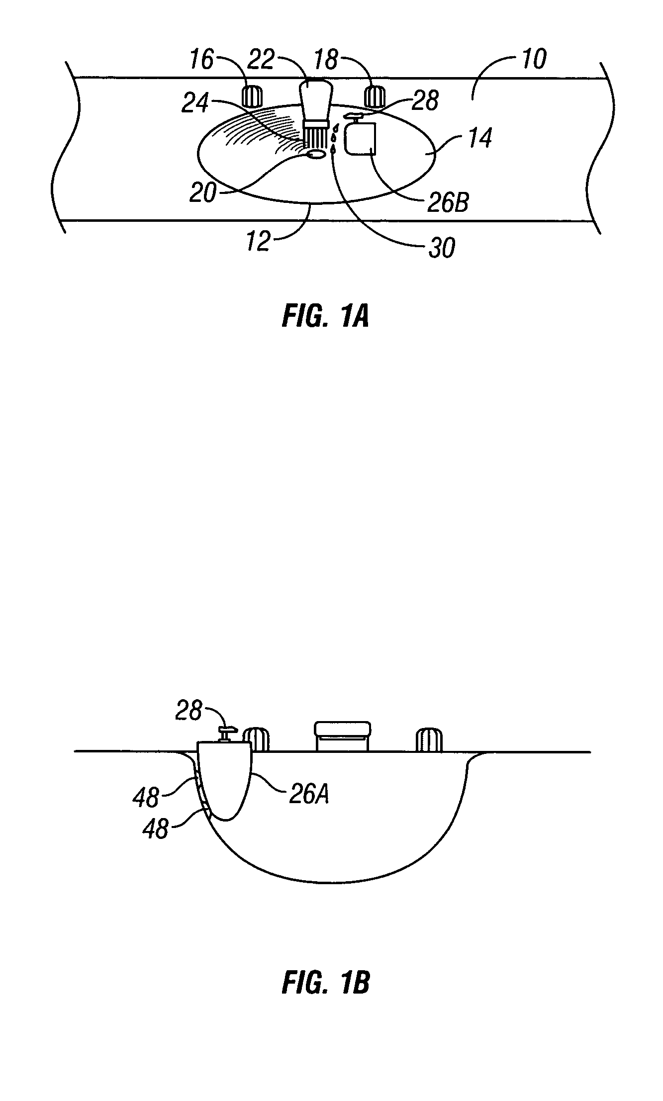
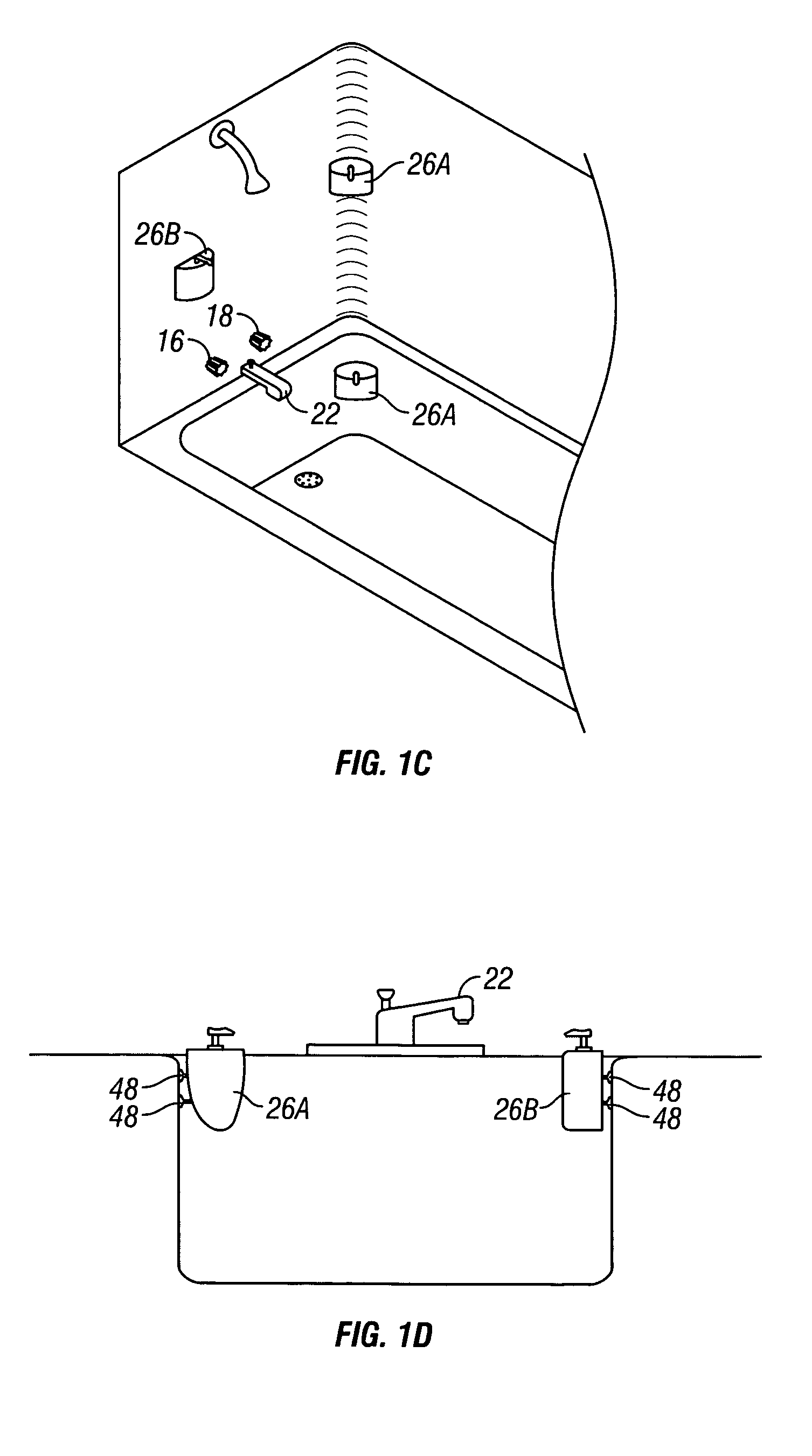
[0051]The present invention provides for a liquid dispenser that can be removeably attached to a sink or other surface using suction cups, preferably height adjustable suction cups. FIGS. 1A-1D illustrate the present invention in various environments. The environments shown are not to be limiting, but merely representative of the environments in which the liquid dispenser of the present invention is used. It should be appreciated that different types of liquid may be used in different environments. The present invention is in no way limited to the particular type of liquid used. The liquid can be, without limitation, soap, shampoo, gel, foam, hair care liquid, a cleaning liquid, or an edible liquid (such as various condiments). FIG. 1A illustrates a bathroom countertop 10. A sink 12 is positioned within the bathroom countertop 10. The sink 12 has an inside surface 14. The inside surface 14 of the sink is typically contoured or sloped inwardly from the countertop 10 to the drain 20 o...


PUM


Abstract

A liquid dispenser includes a body having an inner cavity for containing liquid, and an aperture providing access to the inner cavity. A push pump is fitted within the aperture. At least one height adjustable mount is connected to the body for releasably attaching the body to a surface. Preferably the body is conformingly shaped. An adapter can connect the liquid dispenser to a liquid container for filling the liquid dispenser.

Description

BACKGROUND OF THE INVENTION[0001]The present invention relates to the dispensement of liquids. More particularly, but not exclusively, the present invention relates to a device and method for dispensing liquids such as soap.[0002]Liquid dispensers that incorporate push pumps are found in various places throughout the home, including in the kitchen and bathroom. These liquid dispensers can be used for dispensing soap, lotion, or other types of liquid. Liquid dispensers for dispensing soap are often preferred over using a bar of soap because liquid dispensers are generally cleaner and create less mess than bars of soap. Nevertheless, despite this advantage of liquid dispensers, problems remain. These problems are magnified when young children use liquid dispensers. For example, children often cannot reach the soap on the back of the sink. Therefore, the soap is difficult to dispense for the children, and they may not even use it. Moreover, children may be inclined to pump more soap th...

Claims


Application Information

Patent Timeline
Patent Type & Authority Patents(United States)
IPC IPC(8): B65D88/54A45D42/14B67D7/06A47K5/12B05B11/00G01F11/42
CPCA47K5/12B05B11/3052B05B11/3001A47K2005/1218B05B11/1052B05B11/1001
Inventor BASSETT, WADE M.BASSETT, LISA L.
Owner MBHD ENTERPRISES
Why Eureka
Eureka Blog
Learn More