
Device and process for calibrating geometrical measurements of surgical tools and orienting the same in space

Inactive Publication Date: 2010-06-01
AO TECH AG
View PDF7 Cites 787 Cited by
  • Summary
  • Abstract
  • Description
  • Claims
  • Application Information

AI Technical Summary

Benefits of technology

[0013]because the marking indicators, which are preferably applied on a tool handle, meaning the tool shank at an axial distance, generate a lengthening of the arms encompassing the angle α, so that a small change of the angle α creates an additional increase of the distances between the marking indicators on the tool and those on the device, which makes it possible to achieve a precision greater than that with shiftable jaws;
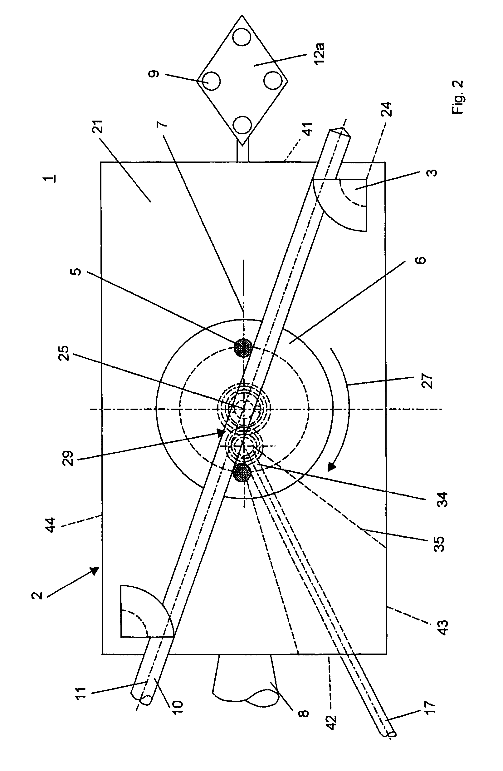
[0016]In a preferred embodiment the jaws are, at least at their opposite surface portions, conformed as double cones and comprise at their axial centre an indentation penetrating across the central axis. The advantage of this conformation is essentially in the fact that the notched portion aids the jaws in positioning an inserted tool in a defined position. The indentations of the jaws are preferably conformed in alignment with each other, whereby the additional effect desirable for a measurement, that of increasing the angle α at increasing diameter, is enhanced because both contact points of the tool are diverging further from the central axes of the jaws.
[0022]The rotary table is preferably movable, through an operating element, against the spring pressure in a second rotating direction around the axis of rotation. This achieves the advantage that the rotary table can, through the operating element, be turned so as to allow inserting a surgical tool between the jaws, or in the case of an inverted rotation, to press it against the jaws. By assisting the one rotating direction by spring pressure and the other by hand pressure, a simple manual handling of the device is assured.
[0026]In an additional embodiment the central axes of the jaws are set vertically to the surface. The jaws are also, at least on the surface portions opposing each other, conformed in a round cylindrical manner, while their surface is shaped in a flat manner. This allows attaining the advantage that flat tools, for instance bits or saw blades can be laid down on the surface without causing a twist between the jaws.

Problems solved by technology

The disadvantage of this known device is that measuring errors may occur if the jaws cannot make proper contact over their entire length.

Method used


Image

  • Device and process for calibrating geometrical measurements of surgical tools and orienting the same in space
  • Device and process for calibrating geometrical measurements of surgical tools and orienting the same in space
  • Device and process for calibrating geometrical measurements of surgical tools and orienting the same in space

Examples


Embodiment Construction

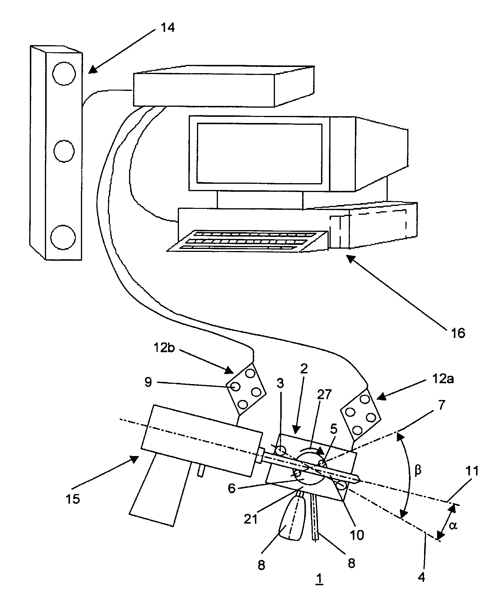
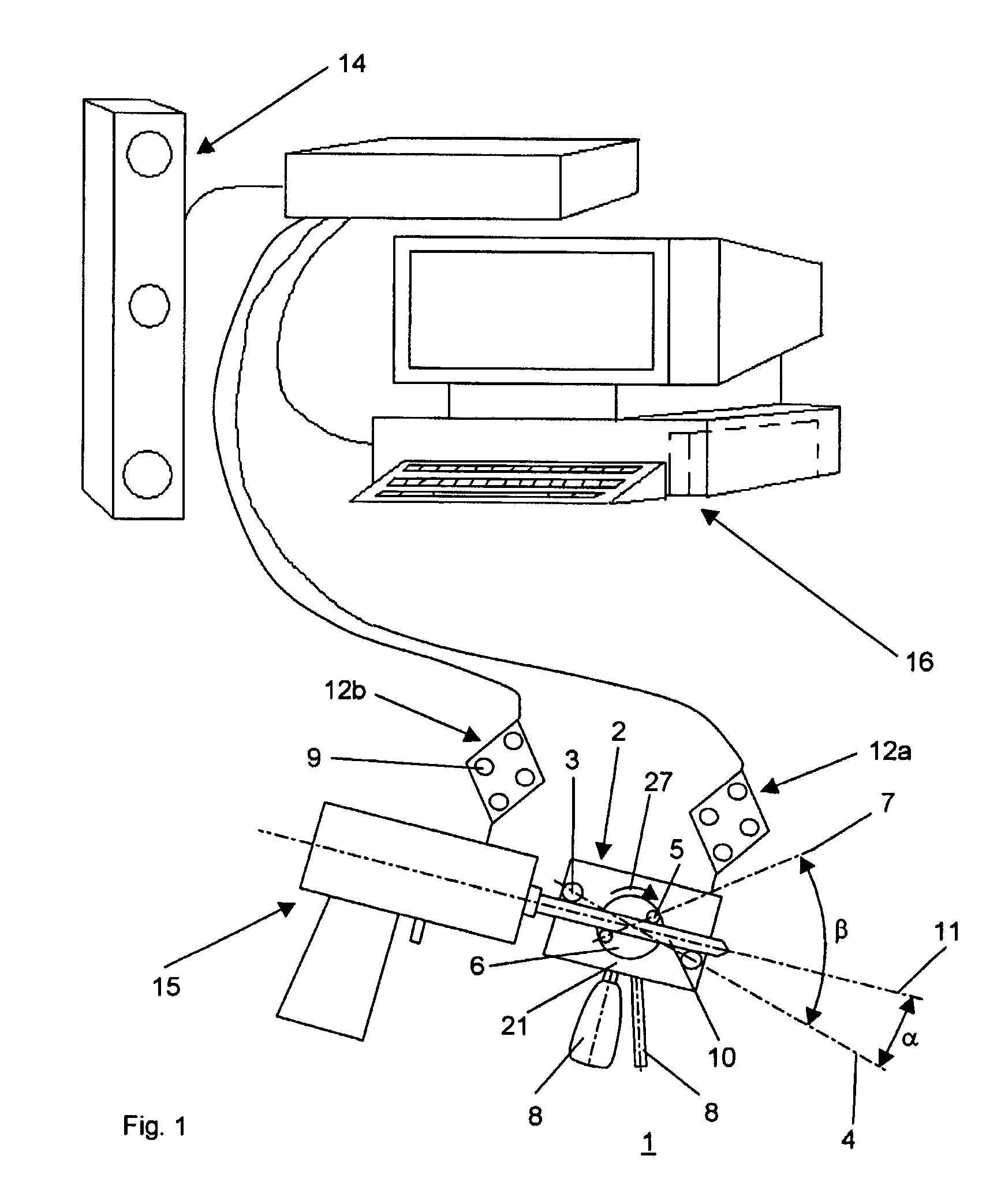
[0035]FIG. 1 shows a form of embodiment of the device 1 which is essentially realized by a docking station 2 fitted with two jaws 3 and a reference device 12a, together with a drill held in a driving machine 15 coaxially to its axis as a surgical tool 10, as well as by a position detecting device 14 and a computer 16. The jaws 3 and the surface 21 encompass a U-shaped passage 18 (FIG. 3) suitable for passing a longitudinal surgical tool 10. The round cylindrical jaws 3 present parallel central axes 24 which are set up centrally to the flat surface 21 of the docking station 2. The surgical tool 10, meaning the drill, is passed through the jaws 3 and rests, through its mantle surface concentric to the longitudinal axis 11, at two points on the jaws 3 and the surface 21, while the longitudinal axis 11 encloses an angle α with one of the reference straight lines 4 crossing the two central axes 24 (FIG. 3) of the jaws 3 at right angles. An additional reference device 12b is provided on t...


PUM


Abstract

A device (1) for calibrating geometrical measurements of surgical tools (10) as well as for orienting the same in space, including: A) a docking station (2) having two jaws (3) and a surface (21); and B) at least three marking indicators (9) firmly attached to the docking station (2) and capable of being measured, in reference to their position in space, electromagnetically or acoustically through a position detecting device (14), where C) the jaws (3) each have a lateral wall (40) so that the surface (21) and the lateral walls (21) of the two jaws (3) enclose a U-shaped passage (18), where D) the two jaws are conformed in a cylindrical or double conical manner; and E) the two lateral walls (40) or the surface (21) present a form comprising at least two additional contact points for a surgical tool (10) inserted between the jaws (3) across its longitudinal axis (11).

Description

BACKGROUND OF INVENTION[0001]1. Field of Invention[0002]The invention refers to a device for calibrating geometric measurements, orienting and positioning of surgical tools in space.[0003]2. Description of Related Art[0004]Such devices are suitable for the calibration of geometric measurements, especially of the diameter, position and / or orientation of surgical tools in space. The calibration of the position and orientation is above all needed for surgical tools employed in computer-assisted surgery, where the position and orientation of various surgical tools is measured, during an operation, while using a surgical navigation system including a position detecting device. Such a navigation system merely allows determining the position of a marking indicator applied to the tool or a machine comprising the tool, for instance a drilling machine. An intra-operative calibration is for instance indispensable for drilling processes where the drill, if inserted into a drilling machine in-si...

Claims


Application Information

Patent Timeline
IPC IPC(8): G01B21/00
CPCA61B19/52A61B19/5244A61B2017/00725A61B90/36A61B34/20A61B2034/207
Inventor LANGLOTZ, FRANKROHRER, URS
Owner AO TECH AG
Learn More