
Flooring system

a floor and system technology, applied in the direction of couplings, cables for vehicles/pulleys, building components, etc., can solve the problems of gap or space remaining, complicated grouting process, and difficult installation, and achieve reliable connection, convenient installation, and pleasant aesthetic appearance.

Active Publication Date: 2010-06-01
MUEHLEBACH MORITZ ANDRE
View PDF24 Cites 179 Cited by
  • Summary
  • Abstract
  • Description
  • Claims
  • Application Information

AI Technical Summary

Benefits of technology

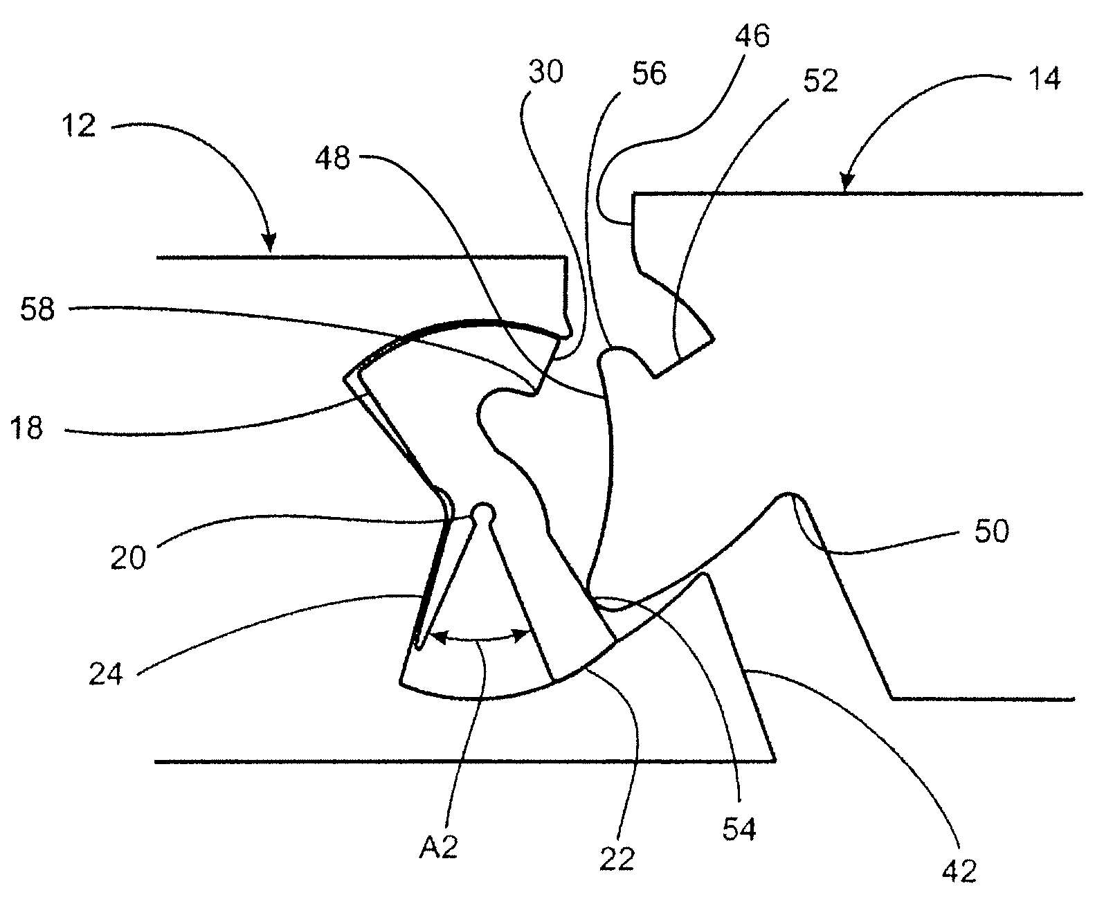
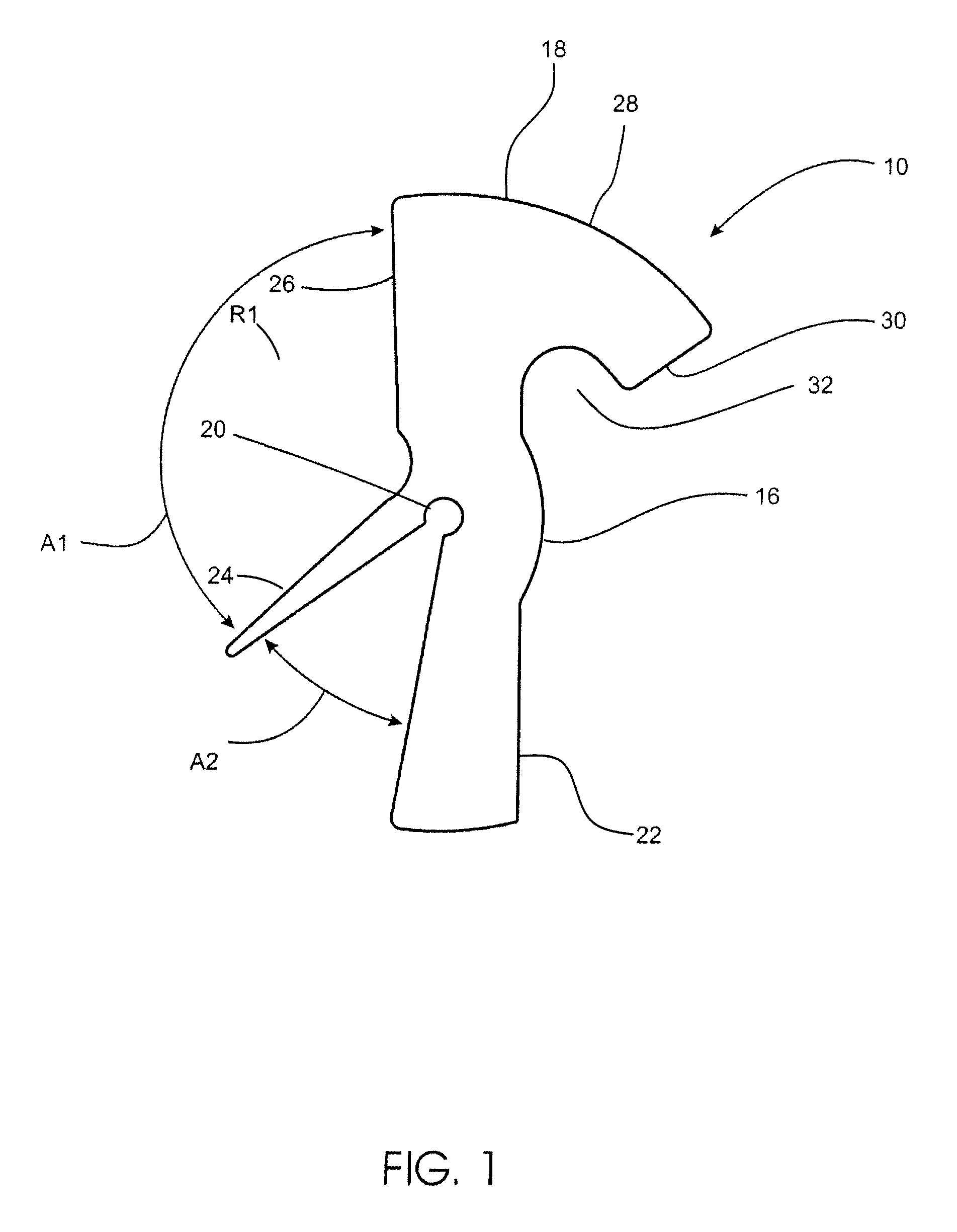
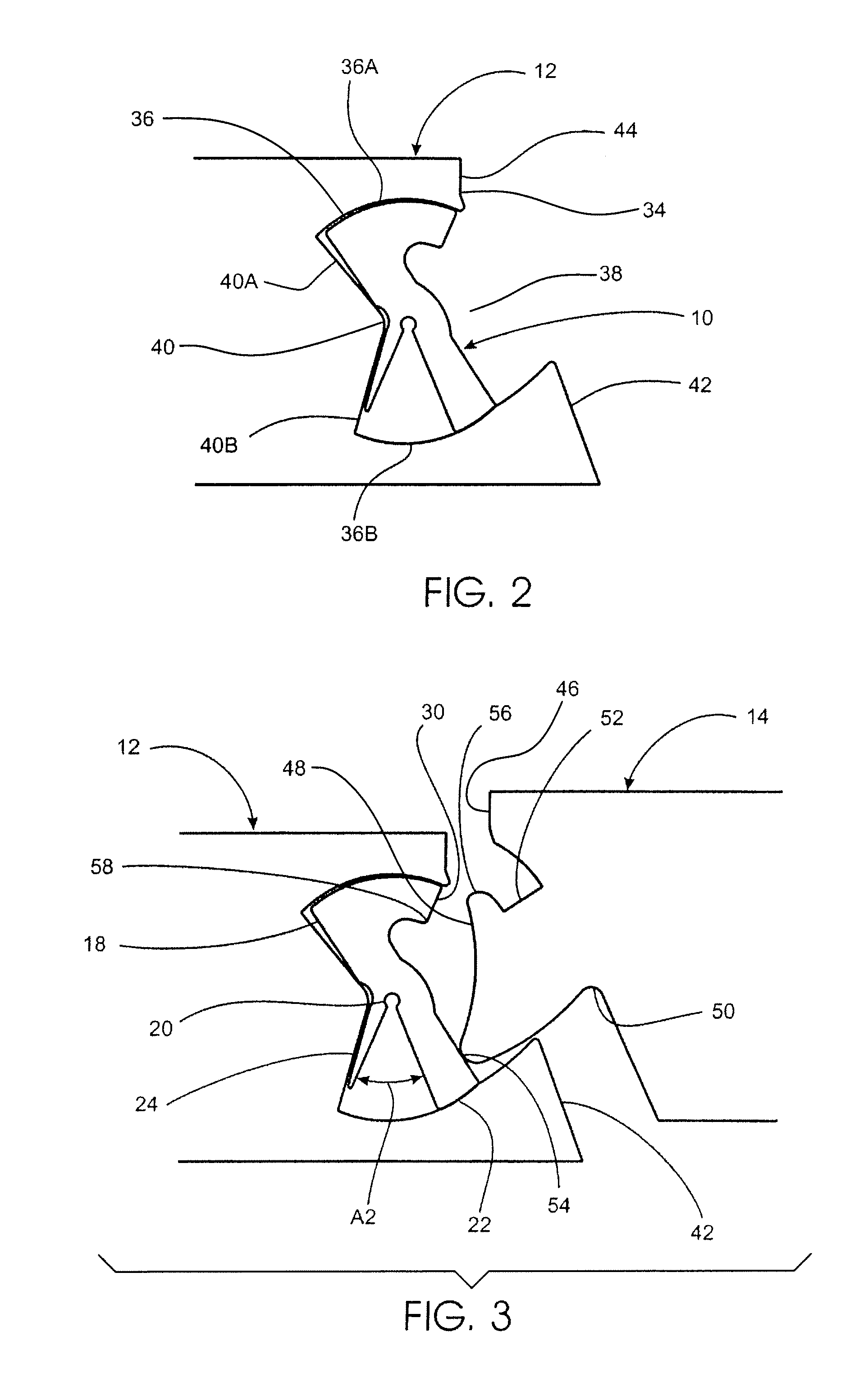
"The present invention provides a mechanical locking joint connection for flooring systems. The interlocking joint has a rotatable cam with a lever portion and a curved portion, which engages with a lower lip and a tongue on the floor panel to create a tight locking connection. The biasing force of the interlocking joint ensures a secure and reliable connection that looks good. The invention is easy to install and results in a pleasant aesthetic appearance."

Problems solved by technology

Fine wood flooring may requiring complicated nailing or gluing techniques in order to lay and connect adjacent flooring panels.
Tile flooring generally requires a grouting process which may be very tedious and complicated.
Related art flooring system joint connections have a disadvantage in that the floor planks when fitted together may not lie completely flush, but instead a gap or space remains between adjacent floor panels.
This may be a particular disadvantage as dust, dirt, or other particles may accumulate in the gaps, creating an unattractive appearance and unsanitary conditions.
Further, most laminate flooring is of the “floating floor” type utilizing an interlocking joint system, which may be considered uncomplicated and easier to install.
However, related joint systems in floor systems generally have the disadvantage of creating a visual disruption in the surface pattern of the laminate flooring.
This significantly detracts from the visual and textural impression of system, resulting in an unattractive appearance of the flooring when it is installed.

Method used


Image

  • Flooring system
  • Flooring system
  • Flooring system

Examples


third embodiment

[0063]the present invention is illustrated in FIGS. 5, 9, 10 and 27. In this embodiment, the rotatable locking member 200 (FIG. 27) is provided with a head 202 at the end of first arm 218 having a substantially convex shape. The rotatable locking member 200 includes a second arm 222 and a resilient arm 224 having shapes similar to second arm 18 and resilient arm 22 in FIGS. 1-4. As illustrated in FIGS. 9 and 10, as the second panel 214 enters the opening 238, the bottom edge 254 of tongue 248 pushes the second arm 222 of the rotatable locking member 200, causing the second arm 222 to rotate towards the resilient arm 224 and causing the first arm 218 to rotate towards the tongue 248 until it presses against the top edge 256 of the tongue 248. The tope edge 256 of the tongue 248 prevents the first arm 218 from rotating any further. Thus as the bottom edge 254 of tongue 248 presses against second arm 222, the second arm 222 bends under increasing force towards the resilient arm 224, wh...

fifth embodiment

[0091]the present invention is illustrated in FIGS. 19 and 20. In this embodiment, rather than an axial extension at the end of a slot member secured into a groove at the rear of a main groove in the first panel 417, this embodiment illustrates an insertion member 500 having a hooked shaped head 502, a second arm 504, a resilient arm 505 and a core aperture 506. What differentiates this embodiment from the previous embodiments is that the rotatable member 500 is secured in place through a protrusion 507 formed into and as part of the back wall of the groove 508. Because it is made from the core material of the first panel 517, this protrusion 507 acts as the axis of rotation around which the rotatable locking member 500 will rotate.

[0092]The operation of the joint is substantially similar to the embodiments heretofore discussed, with the insertion member moving from an open to a closed position as the panels are joined. In this embodiment, the resilient arm 505 engages the rear surf...

sixth embodiment

[0093]A sixth embodiment is illustrated in FIGS. 22 through 26, in which a insertion member having a rotatable portion provided a locking operation in which the rotatable member moves from a closed position, to a open position during locking, back to the closed position after locking. In a first aspect of this invention, illustrated in FIG. 22, insertion member 600 is provided with a rotatable member 602 having a convex head 604. The insertion member 600 has a main body 605 with an arcuate groove 606 formed on an upper surface 607. The insertion member 600 also has a slot insertion portion 603 substantially similar to the slot portion 402 illustrated in FIG. 13. The slot insertion portion 603 may have one or more teeth or flanges 608 that facilitate securing the slot insertion portion 603 into a corresponding slot at the rear of a groove. In addition, rotatable member 602 has a single arm 609 with a rounded or blunt tip 610 shaped and sized to correspond to the arcuate groove 606 fo...


PUM


Abstract

A joint for connecting two adjacent flooring panels together in a substantially vertical manner includes a rotatable locking member made of plastic, metal or another resilient material. The rotatable locking member is located within a groove or opening of one flooring panel and the second flooring panel has a tongue shaped to mate with the rotatable locking member. Upon installation, the rotatable member rotates and locks around the back of the tongue via a groove above the tongue. The rotatable locking member includes a resilient arm which is bent away from its initial rest position upon installation, so that when the rotatable locking member locks onto the tongue, the resilient arm is bent providing a biasing force which holds the panel securely in position.

Description

BACKGROUND OF THE INVENTION[0001]1. Field of the Invention[0002]The present invention generally relates to flooring systems. More particularly, the present invention relates to mechanical locking joints for connecting flooring panels.[0003]2. Discussion of the Related Art[0004]Flooring systems are available in a variety of forms, such as fine wood, tile (e.g. granite, brick, slate, etc.), and concrete. Laminate flooring, such as laminates and high-pressure laminate boards (HPL), may also be a popular substitute for traditional flooring materials as they tend to be generally less expensive to produce. Regardless of which type of flooring is desired, it is generally preferable to the user that installation be simple, such that it is not necessary to hire a professional to install the system.[0005]Methods of installation for flooring systems vary greatly. Fine wood flooring may requiring complicated nailing or gluing techniques in order to lay and connect adjacent flooring panels. Tile...

Claims


Application Information

Patent Timeline
Patent Type & Authority Patents(United States)
IPC IPC(8): E04B2/00
CPCE04F15/02E04F15/04Y10T403/76E04F2201/0552Y10T403/589E04F2201/0138F16B2200/73
Inventor MUEHLEBACH, MORITZ ANDRE
Owner MUEHLEBACH MORITZ ANDRE
Learn More