
Fixed pattern extracting apparatus, pattern writing apparatus, fixed pattern extracting method and recording medium

a technology of pattern writing apparatus and extracting apparatus, which is applied in the direction of originals for photomechanical treatment, instruments, optics, etc., can solve the problems of not being able to extract a plurality of fixed pattern elements from a writing pattern, taking a long time to perform such an operation, and not being able to achieve the effect of high speed and high speed

Inactive Publication Date: 2010-05-18
DAINIPPON SCREEN MTG CO LTD
View PDF7 Cites 0 Cited by
  • Summary
  • Abstract
  • Description
  • Claims
  • Application Information

AI Technical Summary

Benefits of technology

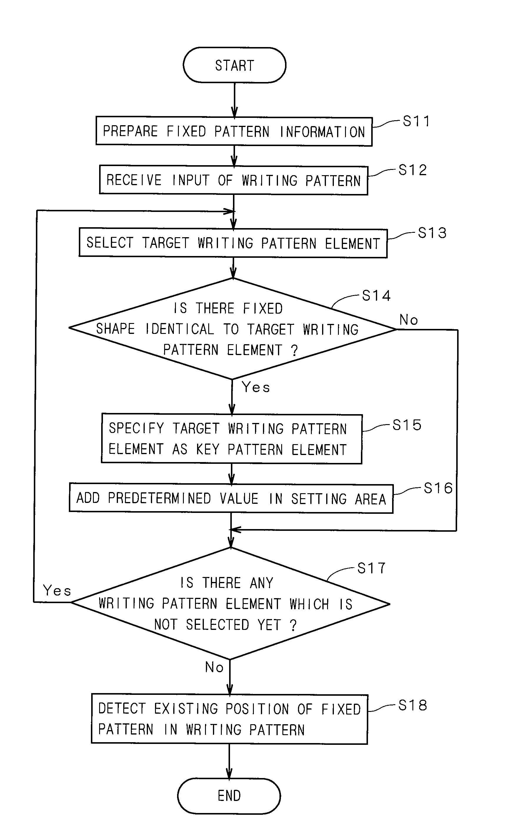
Enables rapid extraction of fixed patterns from writing patterns by efficiently specifying key pattern elements and detecting their positions, reducing the time and complexity involved in comparing all combinations, and handling overlapping areas effectively.

Problems solved by technology

It is not easy, however, to extract a fixed pattern in which a plurality of fixed pattern elements are arranged from a writing pattern, and even if all the combinations of writing pattern elements in the writing pattern are detected to be compared with the fixed pattern, it takes a long time to perform such an operation.
Also by the method of Document 1, it is not possible to extract a plurality of fixed pattern elements from a writing pattern, in consideration of positional relation of the fixed pattern elements.

Method used


Image

  • Fixed pattern extracting apparatus, pattern writing apparatus, fixed pattern extracting method and recording medium
  • Fixed pattern extracting apparatus, pattern writing apparatus, fixed pattern extracting method and recording medium
  • Fixed pattern extracting apparatus, pattern writing apparatus, fixed pattern extracting method and recording medium

Examples


Embodiment Construction

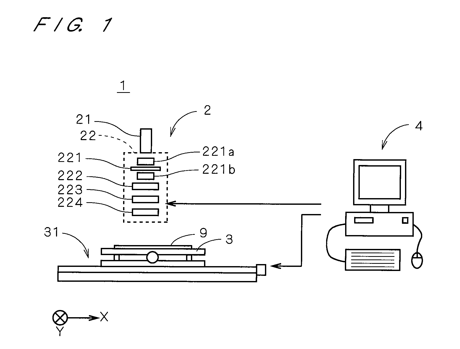
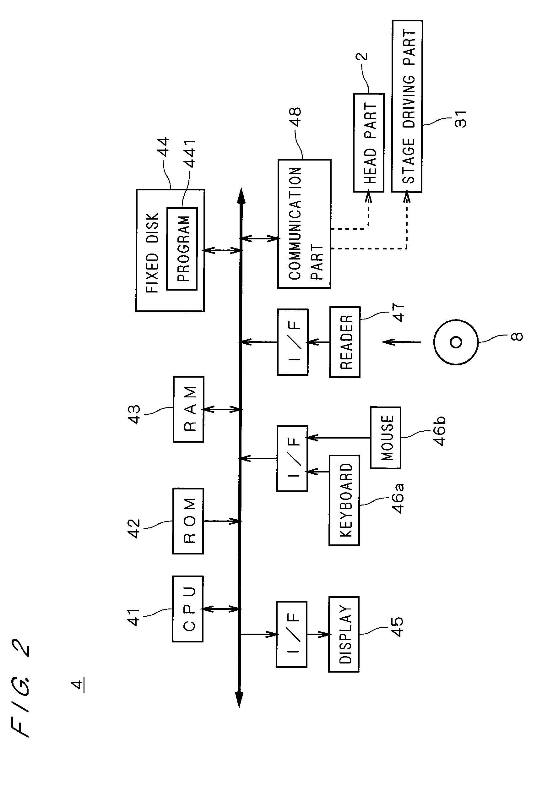
[0043]FIG. 1 is a view showing an overall structure of a pattern writing apparatus 1 in accordance with a first preferred embodiment of the present invention. The pattern writing apparatus 1 comprises a head part 2 for emitting an electron beam for writing, a stage 3 for holding a semiconductor substrate 9, a stage driving part 31 for moving the stage 3 relatively to the head part 2, and a computer 4 connected to the head part 2 and the stage driving part 31. The computer 4 controls the constituent elements of the pattern writing apparatus 1. The stage driving part 31 has a mechanism for moving the stage 3 toward an X direction and a Y direction of FIG. 1.

[0044]The head part 2 has a beam emission part 21 for emitting an electron beam to the substrate 9 and an optical unit 22 for guiding the electron beam to the substrate 9. The optical unit 22 has a mask part 221 in which a plurality of opening patterns corresponding to a plurality of kinds of fixed patterns (i.e., predetermined pat...


PUM


Abstract

In a computer, fixed pattern information indicating respective shapes of fixed pattern elements included in a fixed pattern and respective position vectors of the fixed pattern elements with respect to a reference position in the fixed pattern is prepared and key pattern elements coincident with any of fixed pattern elements are specified from writing pattern elements. Subsequently, a value is added to a position designated by a reverse vector of position vector of a corresponding fixed pattern element with each of the key pattern elements as a starting point in a setting area which corresponds to a writing pattern, and a position is specified to which a value coincident with the number of fixed pattern elements is given, to detect an existing position of the fixed pattern in the writing pattern. It is thereby possible in the computer to extract a fixed pattern from a writing pattern at high speed.

Description

BACKGROUND OF THE INVENTION[0001]1. Field of the Invention[0002]The present invention relates to a technique for extracting a fixed pattern in which a plurality of fixed pattern elements are arranged from a writing pattern in which a plurality of writing pattern elements are arranged to be written on a substrate and also relates to a pattern writing apparatus for writing a pattern on the substrate.[0003]2. Description of the Background Art[0004]In recent years, with high integration of LSIs (Large Scale Integrated Circuits) formed on a semiconductor substrate (hereinafter, referred to as “substrate”), a pattern writing apparatus (also referred to as “electron beam exposure apparatus”) for emitting an electron beam to write a pattern has come into use. In the pattern writing apparatus, each of a plurality of writing pattern elements representing a writing pattern to be written on a substrate is divided into a plurality of rectangle pattern elements, and writing is performed while a s...

Claims


Application Information

Patent Timeline
Patent Type & Authority Patents(United States)
IPC IPC(8): G06K9/00G06F17/50
CPCG06K9/00476H01J37/3026H01J2237/31762G03F1/68G06V30/422
Inventor YAMADA, RYO
Owner DAINIPPON SCREEN MTG CO LTD
Learn More