
Percussive drill bit provided with an improved chuck assembly

a percussive drill and chuck technology, applied in the field of percussive drill bits, can solve the problems of difficult machined components and drill hammers, and achieve the effect of simple and easy manufacturing

Active Publication Date: 2010-05-11
GIEN BERNARD LIONEL
View PDF7 Cites 3 Cited by
  • Summary
  • Abstract
  • Description
  • Claims
  • Application Information

AI Technical Summary

Benefits of technology

The design results in a drill bit that is simpler to manufacture, adaptable to various drill hammer types, and reduces the complexity of assembly, while maintaining operational effectiveness with improved weight distribution and reduced component costs.

Problems solved by technology

There is however a tendency towards drill hammers with bits that do not require these tubes.
The features required on a bit make this component a difficult one to machine.

Method used


Image

  • Percussive drill bit provided with an improved chuck assembly
  • Percussive drill bit provided with an improved chuck assembly
  • Percussive drill bit provided with an improved chuck assembly

Examples


Embodiment Construction

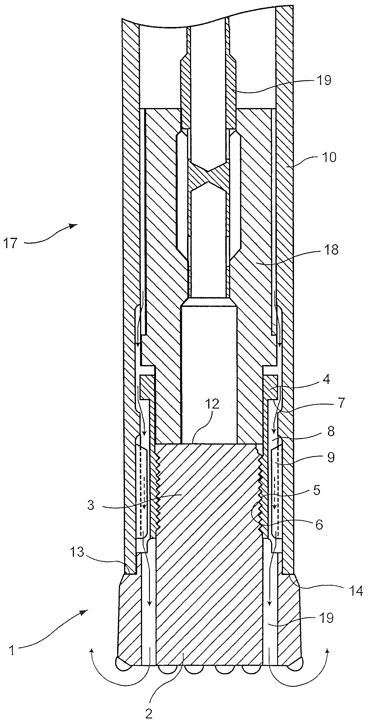
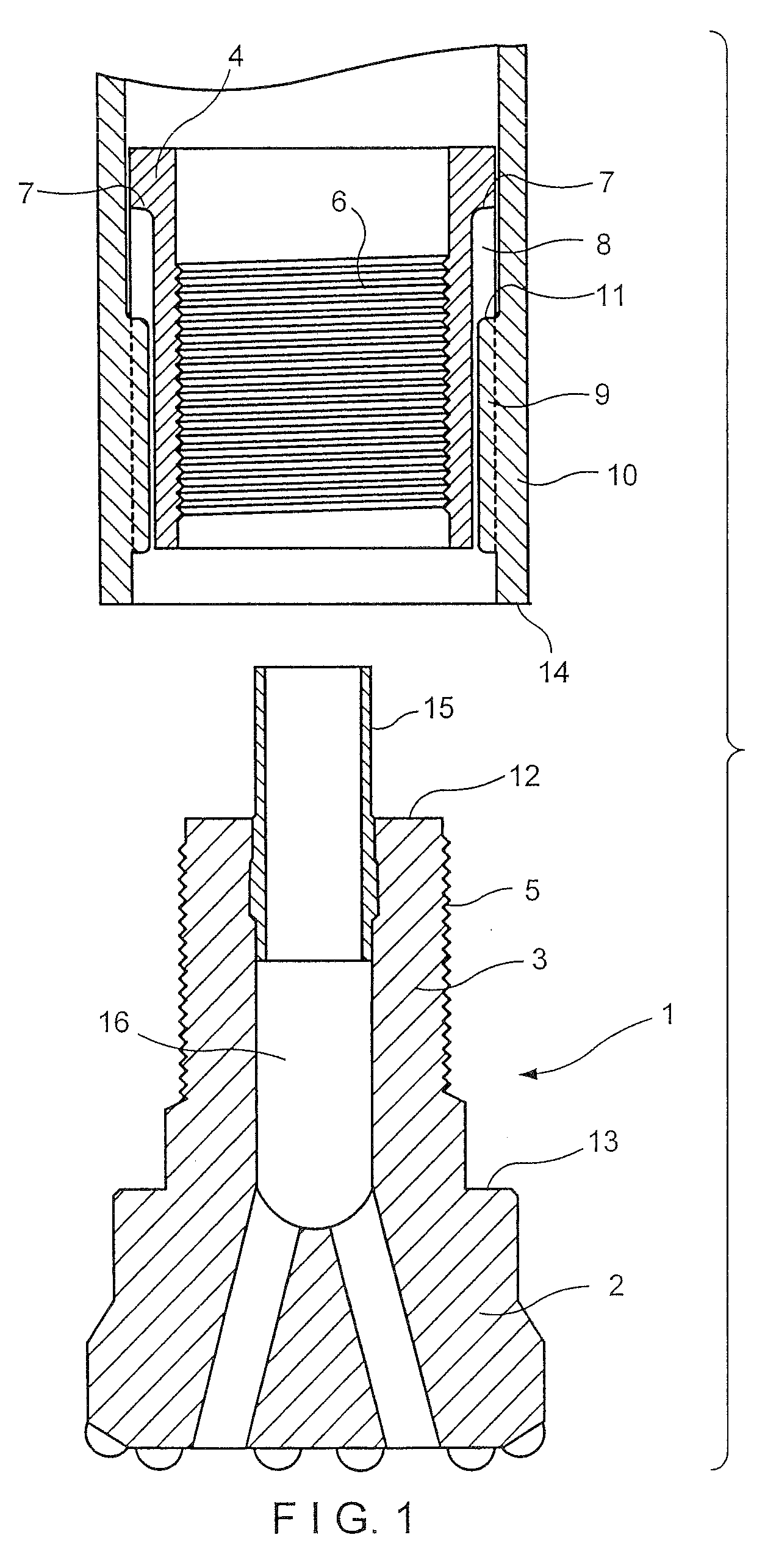
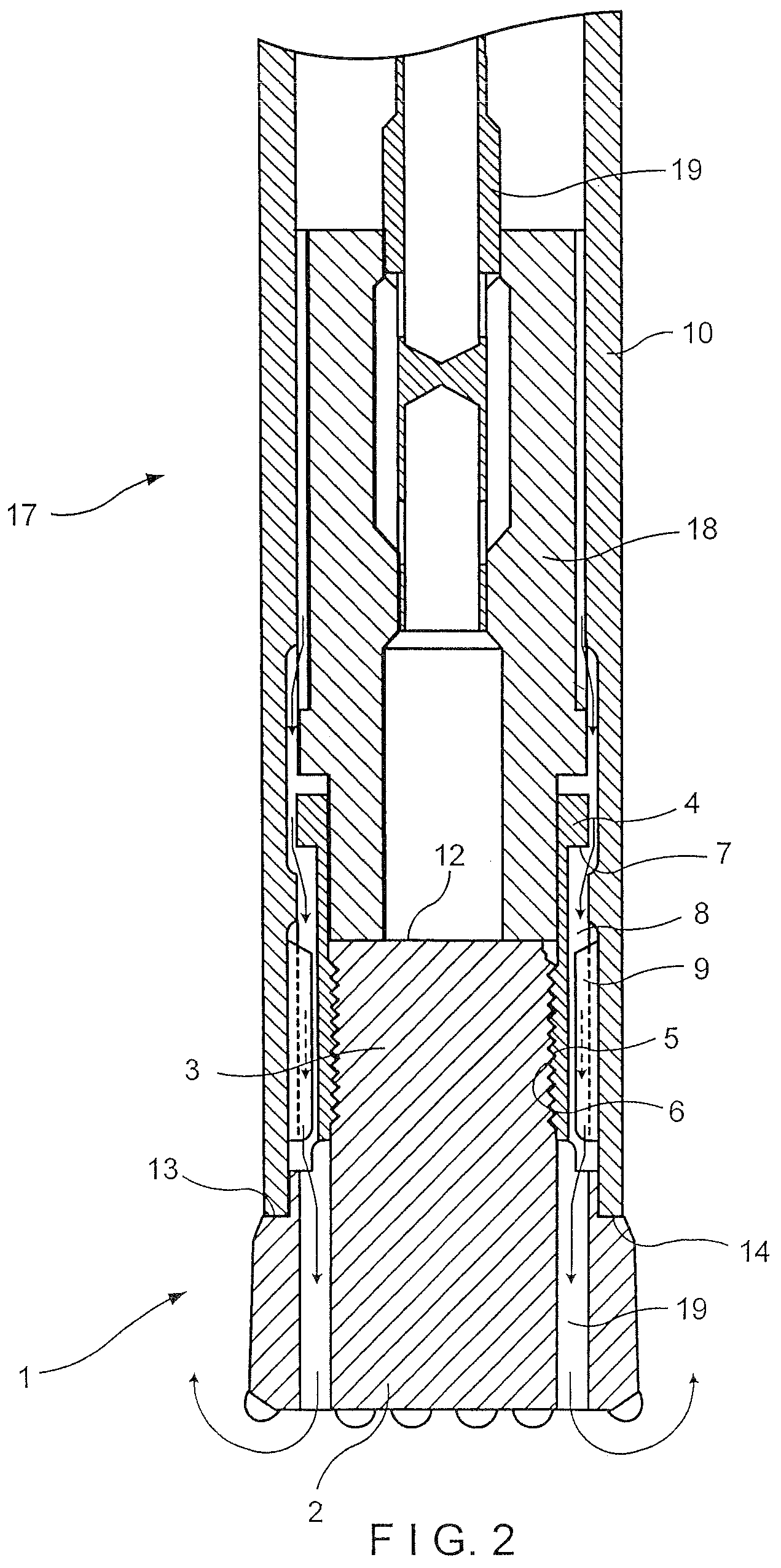
[0014]Referring to FIG. 1, a drill bit (1) is shown having a head (2) at its forward end. Extending from the head (2) is a shank (3) which is adapted to be releasably secured in a reciprocating chuck (4). The shank (3) has screw threads (5) along its length. The chuck (4) is provided as a sleeve, with corresponding screw threads (6) along its inside adjacent its forward end.

[0015]An outwardly or laterally extending shoulder (7) is provided at the rear end of the chuck (4). The exterior of the chuck (4) from the shoulder (7) to its forward end is splined with the shoulder (7) formed between the splines (8). The splines (8) of the chuck (4) engage in corresponding splines (9) in the wear sleeve or housing (10) of a drill hammer. The rear end of each of the splines (9) provides a shoulder (11) to retain the chuck (4) in the wear sleeve (10).

[0016]When the drill hammer is assembled, the chuck (4) is inserted from the rear of the wear sleeve (10). The chuck (4) slides forward and once th...


PUM

PropertyMeasurementUnit
lengthaaaaaaaaaa
areaaaaaaaaaaa
diameteraaaaaaaaaa

Abstract

A percussive drill bit provided with an improved chuck assembly for a down-the-hole drill hammer. The bit has a head at its forward end with a shank extending from the head. The shank is screw threaded along its length. A reciprocating chuck is provided as a sleeve with internal screw thread as corresponding to those of the shank. The shank is releasably secured in the chuck with the read end of the shank providing a striking face. An arrangement of external splines on the chuck, and a retaining shoulder at its rear end, provide for the required guided movement of the chuck within a drill hammer wear sleeve.

Description

FIELD OF THE INVENTION[0001]The invention relates to a drill bit and more particularly to a percussive drill bit with an improved chuck assembly for a down-the-hole drill hammer.BACKGROUND TO THE INVENTION[0002]Drill bits of this kind conventionally have a shank which fits inside the drill housing and an exposed head at the forward end. The head is provided with teeth on a drilling face at its working end. The shank has splines which are engaged by corresponding splines in a chuck secured in the drill hammer. The rear end of the bit shank forms a striking face onto which a reciprocating piston hammer impacts during operation. Between the striking face and the splines, is a section of reduced diameter. This section defines a pair of shoulders between which a retaining ring, normally above the chuck, slidably engages the bit. The section of reduced diameter has to be longer than the axial thickness of the retaining ring. This allows for the necessary axial or longitudinal movement of ...

Claims


Application Information

Patent Timeline
Patent Type & Authority Patents(United States)
IPC IPC(8): E21B10/38
CPCE21B17/076E21B10/36
Inventor GIEN, BERNARD LIONEL
Owner GIEN BERNARD LIONEL
Learn More