Adapter card structure

a technology of adapter card and card body, which is applied in the direction of coupling device connection, two-part coupling device, securing/insulating coupling contact member, etc., can solve the problems of difficult mold manufacturing, inability to precisely control the dimensions, and even smaller dimensions of the slide switch, so as to improve the elasticity and facilitate the manufacture. , the effect of clear click

Inactive Publication Date: 2009-02-03
JESS-LINK PRODUCTS
View PDF3 Cites 7 Cited by
  • Summary
  • Abstract
  • Description
  • Claims
  • Application Information

AI Technical Summary

Benefits of technology

[0009]The present invention has the following effect: A wave-shaped perpendicular plate is formed by bending and extending the outermost of the terminals. The wave-shaped plate is arranged to engage with the slide switch and has a better elasticity than the plastic protrusion used in the prior art, so that the user can feel a clearer click when pushing the slide switch, thereby understanding whether the slide switch has been pushed to a proper position or not. At the same time, the construction of the wave-shaped plate is simpler and easy to manufacture than plastic protrusions, thereby reducing the production cost.

Problems solved by technology

However, the dimensions of such adapter cards are small, and thus the dimensions of the slide switch are even smaller.
If the casing and the slide switch are molded including their protruding points and recess, respectively, the manufacture of the associated molds is difficult, and it is not easy to control the dimensions precisely.
As a result, the protruding points and the recess may not correspond to each other very well, so that after operating the slide switch, a user cannot be sure whether the slide switch has been pushed to the correct position.

Method used


Image

  • Adapter card structure
  • Adapter card structure
  • Adapter card structure

Examples


Embodiment Construction

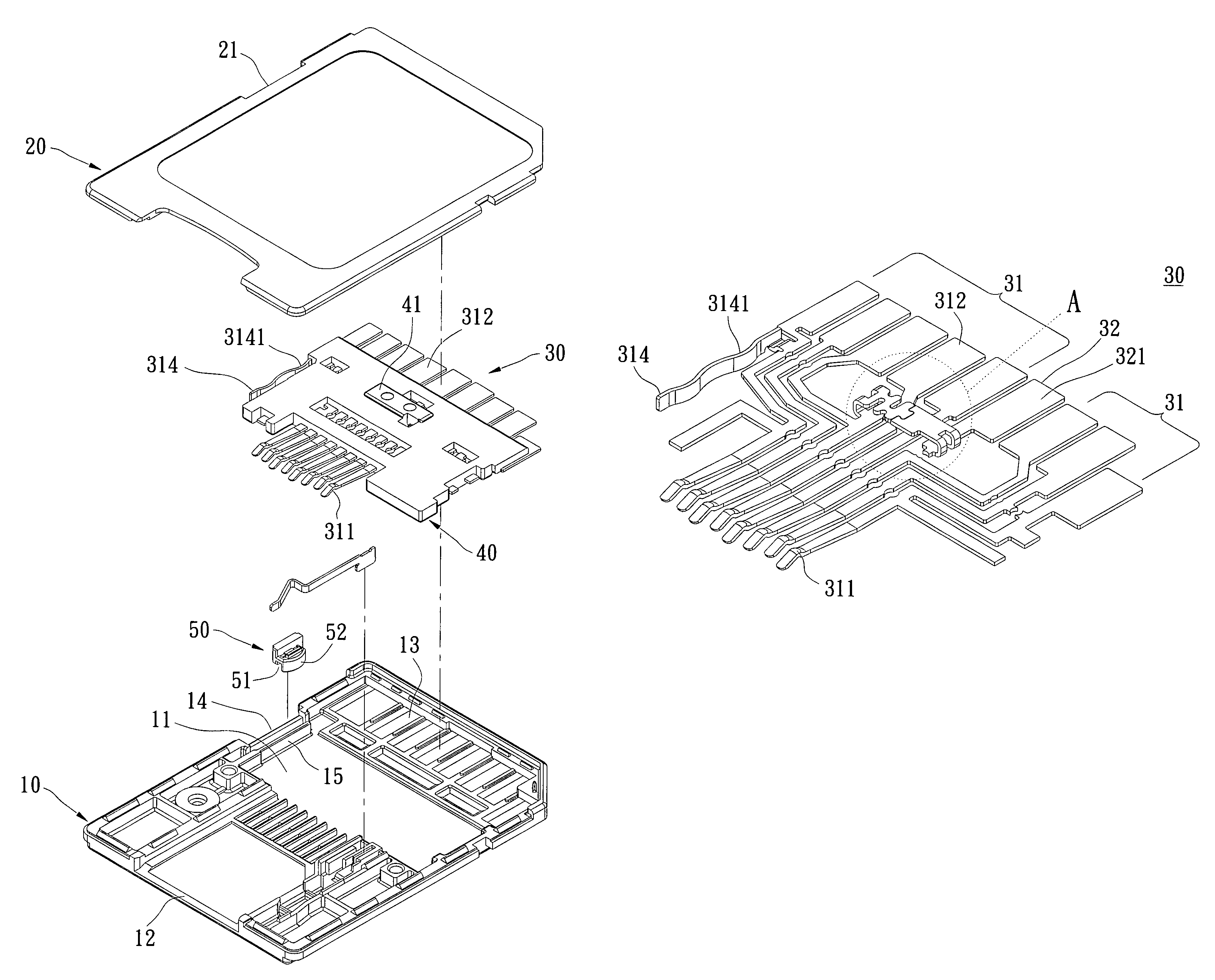
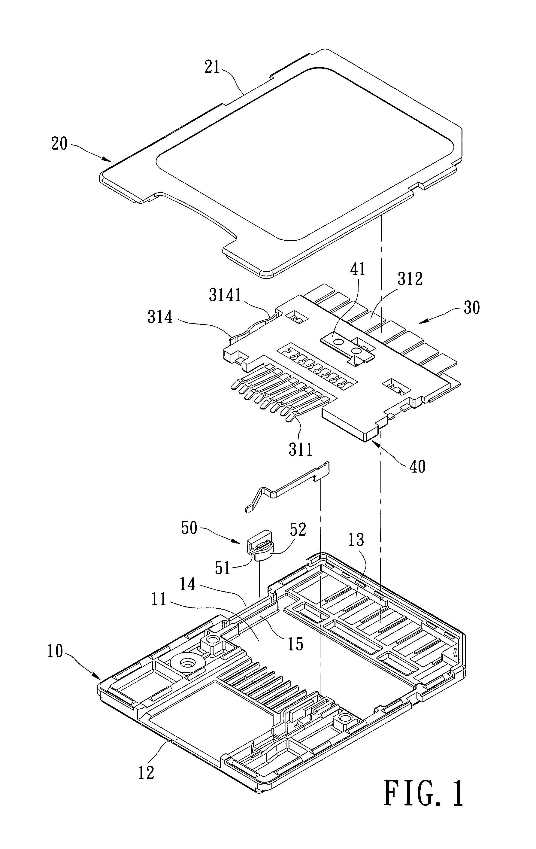
[0017]Please refer to FIGS. 1 to 4. The adapter card structure of the present invention includes a lower cover 10, an upper cover 20, a terminal set 30, an insulating plate 40 and a slide switch 50.

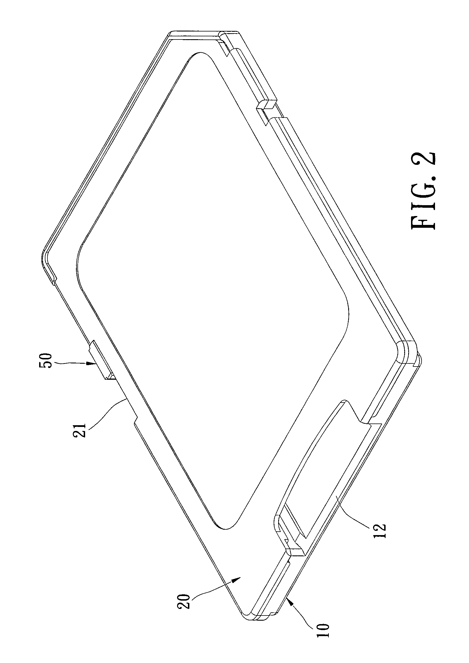
[0018]The lower cover 10 is made of insulating plastic materials. The lower cover 10 is provided with a cavity 11 at a position near the center thereof to accommodate an adapter card. The front end of the lower cover 10 is provided with an insertion port 12 for allowing an adapter card (not shown) to be inserted therein. The rear end of the lower cover 10 is provided with a plurality of openings 13. The left side of the lower cover 10 is provided with a notch 14. The bottom surface of the cavity 11 is provided with a rib 15 at a position adjacent to the notch 14.

[0019]The upper cover 20 is made of insulating plastic materials and covers the lower cover 10. The left side of the upper cover 20 is provided with a notch 21 to correspond to notch 14 of the lower cover 10.

[0020]The terminal set...


PUM


Abstract

An adapter card structure includes a lower cover, an upper cover, an insulating plate, a terminal set and a slide switch. The upper cover covers the lower cover. The insulating plate is lodged between the upper cover and the lower cover. The terminal set comprises a plurality of terminals and an independent terminal. The terminals and the independent terminal are inserted into the insulating plate at intervals. A middle section of one of the terminals is connected with a middle section of the independent terminal to form a short circuit portion. A wave-shaped perpendicular plate is formed by means of bending and extending from the outermost one of the terminals. The slide switch is movably provided between the upper cover and the lower cover to engage with the wave-shaped plate. Via this arrangement, a user can have a clear click feeling when pushing the slide switch.

Description

BACKGROUND OF THE INVENTION[0001]1. Field of the Invention[0002]The present invention relates to an adapter card structure, and in particular to a data storage adapter card structure for connecting a data storage adapter card to another adapter card.[0003]2. Description of Related Art[0004]Conventional adapter cards are usually provided at one side of their casing with a slide switch. The side of the slide switch facing the casing is provided with a recess. The casing is provided with two protruding points to engage with the recess of the slide switch. The slide switch can be positioned at the two protruding points via the recess, so that the adapter card can be switched between a write enabled and write protected state.[0005]However, the dimensions of such adapter cards are small, and thus the dimensions of the slide switch are even smaller. If the casing and the slide switch are molded including their protruding points and recess, respectively, the manufacture of the associated mo...

Claims


Application Information

Patent Timeline
Patent Type & Authority Patents(United States)
IPC IPC(8): H01R13/40
CPCH01R13/701H01R13/713H01R31/06H01R12/57H01R12/721
Inventor CHI, HSUEH-JUNG
Owner JESS-LINK PRODUCTS
Why Eureka
Try Eureka