
Spirally wound tube with voids and method for manufacturing the same

a tube and void technology, applied in the field of tubes, can solve the problems of substantial compressive force, difficult or impossible to remove the tube from the winding apparatus without destroying the tube, etc., and achieve the effect of facilitating torque transmission and enhancing id stiffness

Active Publication Date: 2010-05-11
SONOCO DEV INC
View PDF17 Cites 5 Cited by
  • Summary
  • Abstract
  • Description
  • Claims
  • Application Information

AI Technical Summary

Benefits of technology

The non-radial spokes and voids significantly improve the tube's ability to resist inner diameter reduction, allowing for easier removal from winding apparatuses while maintaining structural integrity and cost-effectiveness.

Problems solved by technology

The winding tension required for winding a stable roll of such materials results in substantial compressive forces being exerted by the wound material on the tube in the radially inward direction.
If the tube inner diameter shrinks too much as a result of the forces imposed by the wound material, it can be difficult or impossible to remove the tube from the winding apparatus without destroying the tube.

Method used


Image

  • Spirally wound tube with voids and method for manufacturing the same
  • Spirally wound tube with voids and method for manufacturing the same
  • Spirally wound tube with voids and method for manufacturing the same

Examples


Embodiment Construction

[0023]The present invention now will be described more fully hereinafter with reference to the accompanying drawings in which some but not all embodiments of the invention are shown. Indeed, this invention may be embodied in many different forms and should not be construed as limited to the embodiments set forth herein; rather, these embodiments are provided so that this disclosure will satisfy applicable legal requirements. Like numbers refer to like elements throughout.

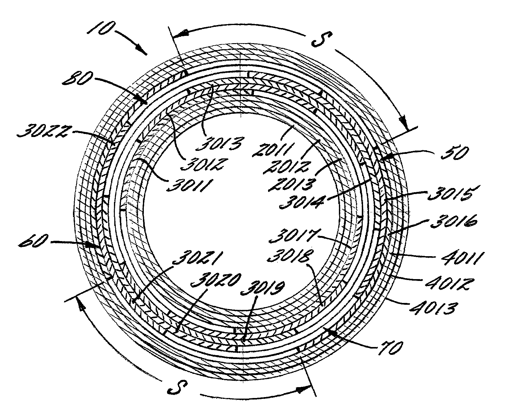
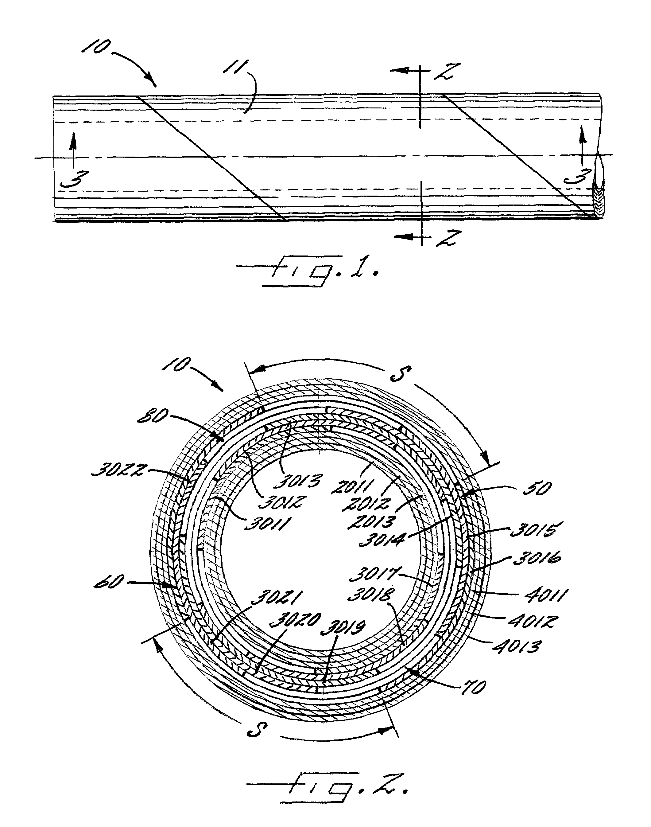
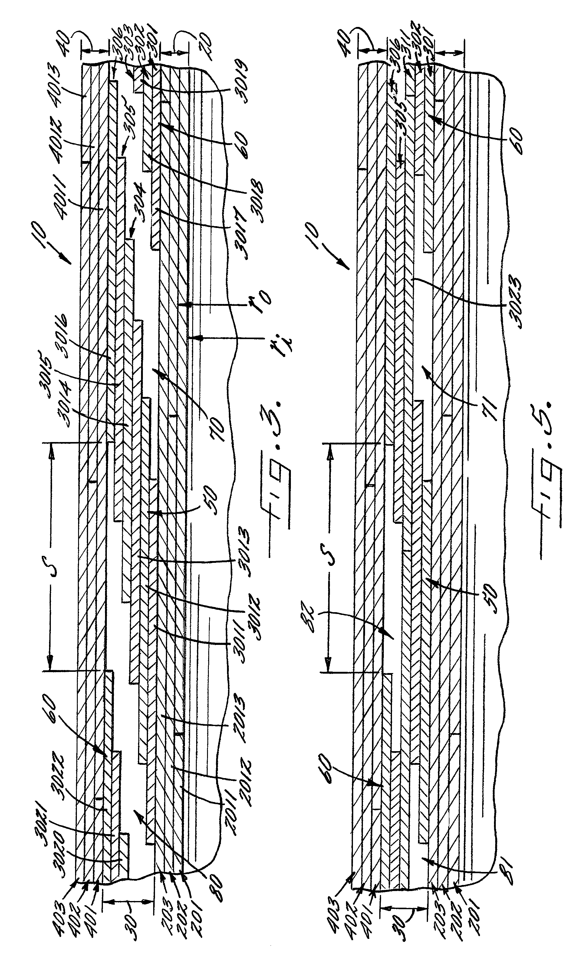
[0024]FIGS. 1 through 3 show a spirally wound tube 10 in accordance with one embodiment of the present invention. The tube 10 extends around and along an axis for a predetermined length from a first end to a second end. As best shown in FIG. 2, the cross-section of the tube relative to the axis defines a circumference.

[0025]As illustrated in FIG. 3, the tube includes a wall 11 having an inner zone 20, an intermediate zone 30, and an outer zone 40. The inner zone 20 is located inwardly and radially extends from an in...


PUM

PropertyMeasurementUnit
ID stiffnessaaaaaaaaaa
inner diameteraaaaaaaaaa
diameteraaaaaaaaaa

Abstract

A tube having enhanced inner diameter stiffness is provided. The tube includes a wall having an inner zone, intermediate zone, and an outer zone. The intermediate zone includes a plurality of partially offset and overlapped plies that form a number of non-radial spokes and voids extending from the inner zone and the outer zone. The non-radial spokes of the tube facilitate the transmission of torque from the inner zone to the outer zone during winding and handling operations, while insulating the inner diameter from radial pressure on the outer zone. The spokes and voids may essentially extend around the entire circumference and length of the tube and thus provide for more consistent properties throughout the tube.

Description

BACKGROUND OF THE INVENTION[0001]1) Field of the Invention[0002]The invention relates to tubes made by spirally winding a plurality of paperboard plies about a forming mandrel and adhering the plies together.[0003]2) Description of Related Art[0004]Spirally wound tubes are used in a variety of applications in which radially inward compressive forces are imposed on the outside diameter of the tubes. For example, continuous materials such as paper, plastic film, metal sheet, and textiles are commonly wound about winding cores formed of spirally wound paperboard tubes. The winding tension required for winding a stable roll of such materials results in substantial compressive forces being exerted by the wound material on the tube in the radially inward direction. Such forces are in a direction to tend to force the inner diameter of the tube to shrink in size. This phenomenon has been referred to as “ID comedown.”[0005]The degree to which a given paperboard tube resists such inner diamet...

Claims


Application Information

Patent Timeline
Patent Type & Authority Patents(United States)
IPC IPC(8): F16L11/00
CPCB31C3/00Y10T428/1369Y10T428/1303Y10T428/1393
Inventor VAN DE CAMP, JOHANNES WILHELMUS
Owner SONOCO DEV INC
Learn More