Multilayer capacitor

a multi-layer capacitor and capacitor technology, applied in the direction of capacitors, fixed capacitor details, fixed capacitors, etc., can solve problems such as sound in the substrate, and achieve the effect of preventing mechanical strain

Active Publication Date: 2010-05-04
TDK CORPARATION
View PDF10 Cites 0 Cited by
  • Summary
  • Abstract
  • Description
  • Claims
  • Application Information

AI Technical Summary

Benefits of technology

[0005]An object of the present invention is to provide a multilayer capacitor capable of preventing mechanical strain caused by electrostrictive effect in the capacitor element body with the dielectric property, from being transmitted to the first and second terminal electrodes.

Problems solved by technology

When the multilayer capacitor is mounted on an external substrate or the like, occurrence of such mechanical strain causes the vibration due to the mechanical strain to be transmitted through the first and second terminal electrodes to the external substrate or the like, and the transmission of vibration due to the mechanical strain to the external substrate or the like results in sounding in the substrate.

Method used


Image

  • Multilayer capacitor
  • Multilayer capacitor
  • Multilayer capacitor

Examples


Embodiment Construction

[0046]The preferred embodiments of the present invention will be described below in detail with reference to the accompanying drawings. In the description, the same elements or elements with the same functionality will be denoted by the same reference symbols, without redundant description.

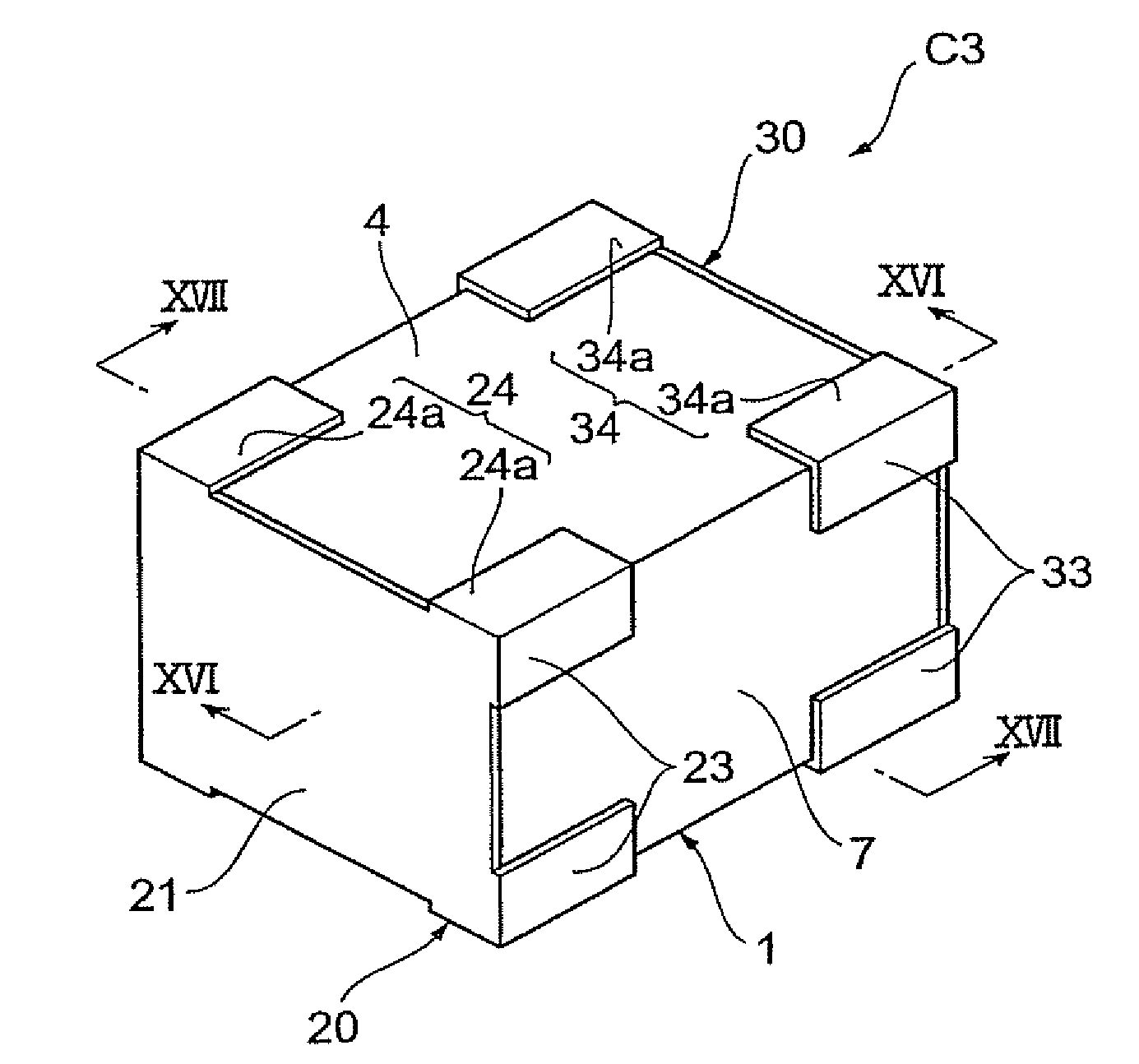
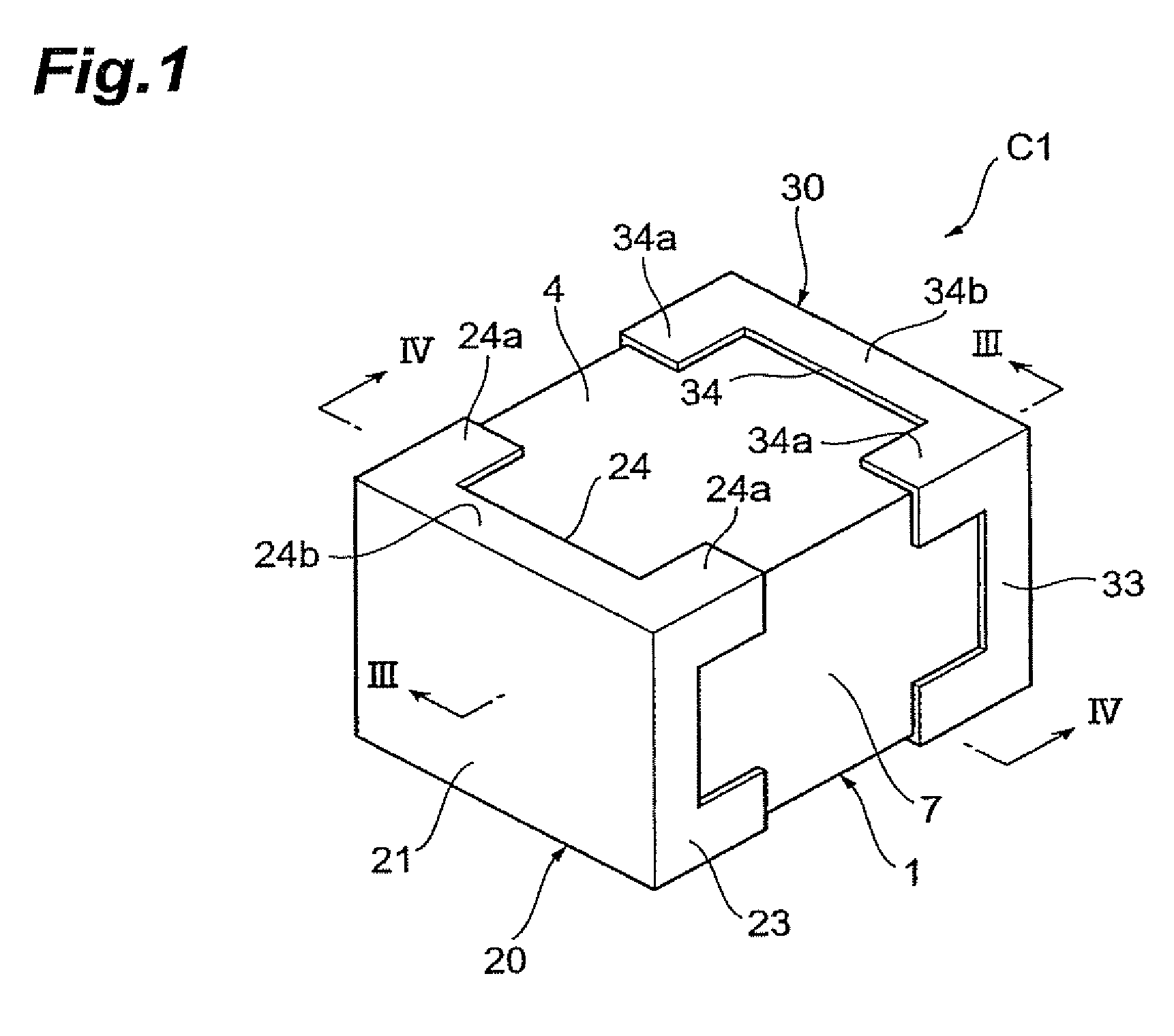
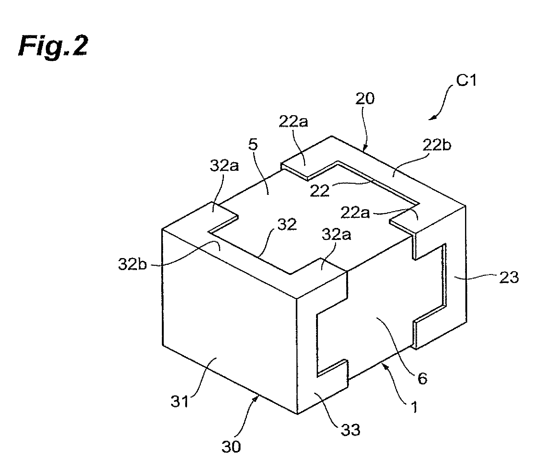
[0047]A configuration of a multilayer capacitor C1 according to an embodiment of the present invention will be described with reference to FIGS. 1 to 5. FIG. 1 is a schematic perspective view showing the multilayer capacitor of the present embodiment. FIG. 2 is a schematic perspective view showing the multilayer capacitor of the present embodiment. FIG. 3 is a drawing showing a sectional configuration along line III-III in FIG. 1. FIG. 4 is a drawing showing a sectional configuration along line IV-IV in FIG. 1. FIG. 5 is an exploded perspective view for explaining a configuration of a capacitor element body.

[0048]The multilayer capacitor C1, as shown in FIGS. 1 to 4, is provided with a capacitor e...


PUM


Abstract

A first terminal electrode has a first electrode portion disposed on a first face and connected to a first internal electrode, and a second electrode portion disposed on a third face and connected to the first electrode portion. A second terminal electrode has a first electrode portion disposed on a second face and connected to a second internal electrode, and a second electrode portion disposed on the third face and connected to the first electrode portion. Each of the second electrode portions of the first and second terminal electrodes, when viewed along a second direction perpendicular to the third face, is arranged with a gap in a third direction perpendicular to the second directions so as to sandwich at least a portion of an end in the first direction of an element body region sandwiched between the first internal electrode and the second internal electrode, at an end in the first direction of the second electrode portion.

Description

BACKGROUND OF THE INVENTION[0001]1. Field of the Invention[0002]The present invention relates to a multilayer capacitor.[0003]2. Related Background Art[0004]A known multilayer capacitor is one having a capacitor element body with a dielectric property having first and second faces facing each other, and a third face extending in a first direction in which the first and second faces face each other, so as to connect the first and second faces; a first internal electrode with an end exposed in the first face and a second internal electrode with an end exposed in the second face, the first and second internal electrodes being arranged in the capacitor element body so as to face each other in a second direction perpendicular to the first direction and to the third face, while sandwiching at least a portion of the capacitor element body; a first terminal electrode connected to the first internal electrode; and a second terminal electrode connected to the second internal electrode (e.g., ...

Claims


Application Information

Patent Timeline
Patent Type & Authority Patents(United States)
IPC IPC(8): H01G4/228
CPCH01G4/30H01G4/232
Inventor TOGASHI, MASAAKIWADA, TAKESHI
Owner TDK CORPARATION
Why Eureka
Try Eureka