
Method of measuring multiphase flow using a multi-stage flow meter

a flow meter and multi-phase technology, applied in the direction of volume/mass flow measurement, measurement devices, instruments, etc., can solve the problem of interfering or temporarily halting fluid production

Active Publication Date: 2010-05-04
BAKER HUGHES INC
View PDF8 Cites 29 Cited by
  • Summary
  • Abstract
  • Description
  • Claims
  • Application Information

AI Technical Summary

Benefits of technology

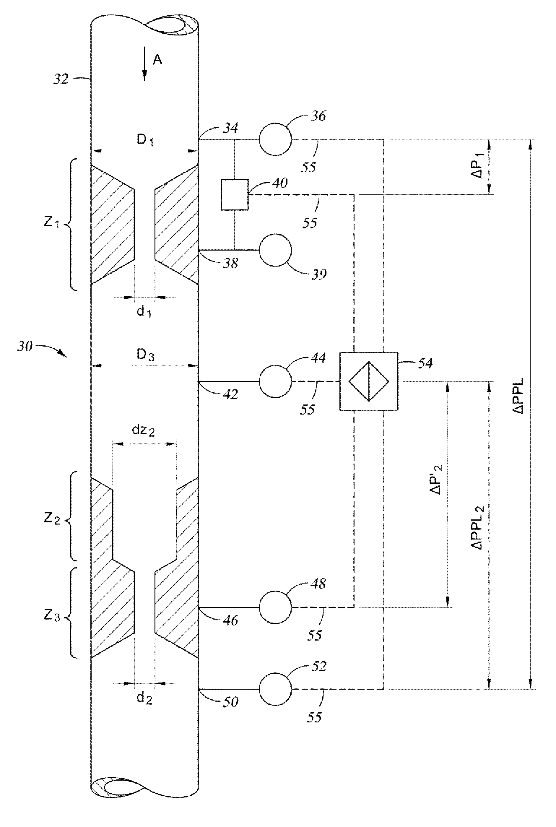
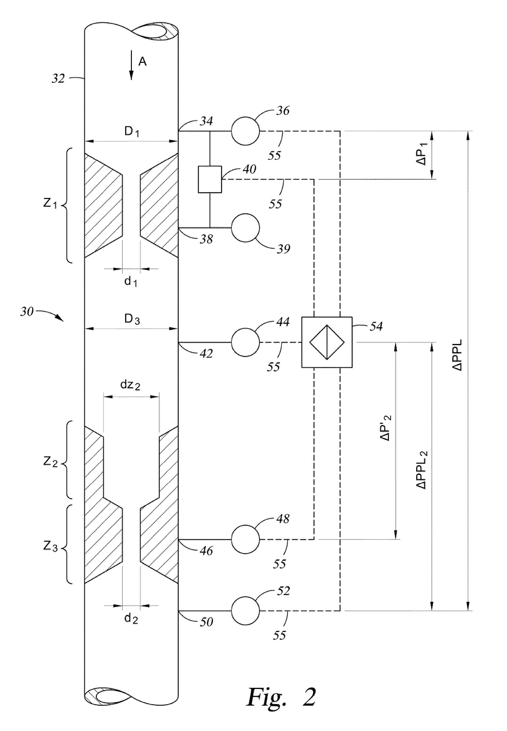
The patent describes methods for estimating the flow of multi-phase fluids through a flow meter, which involves measuring fluid conditions and using an algorithm to calculate the fluid flow rate based on the measured conditions. The methods involve measuring pressure and temperature at the flow meter exit and estimating the gas and water fractions in the fluid. These methods can be used in hydrocarbon producing wellbores to measure the flow of produced fluids. The technical effects of the patent are improved accuracy in estimating the flow of multi-phase fluids and improved reliability in measuring the gas and water fractions in the fluid.

Problems solved by technology

However, these often require periodic analysis of the fluid entering the flowmeter.
This may involve deploying a sample probe upstream of the flowmeter; which can produce inaccuracy, and may interrupt or temporarily halt fluid production.

Method used


Image

  • Method of measuring multiphase flow using a multi-stage flow meter
  • Method of measuring multiphase flow using a multi-stage flow meter
  • Method of measuring multiphase flow using a multi-stage flow meter

Examples


Embodiment Construction

[0011]The present invention will now be described more fully hereinafter with reference to the accompanying drawings in which embodiments of the invention are shown. This invention may, however, be embodied in many different forms and should not be construed as limited to the illustrated embodiments set forth herein; rather, these embodiments are provided so that this disclosure will be thorough and complete, and will fully convey the scope of the invention to those skilled in the art. Like numbers refer to like elements throughout. For the convenience in referring to the accompanying figures, directional terms are used for reference and illustration only. For example, the directional terms such as “upper”, “lower”, “above”, “below”, and the like are being used to illustrate a relational location.

[0012]It is to be understood that the invention is not limited to the exact details of construction, operation, exact materials, or embodiments shown and described, as modifications and equ...


PUM


Abstract

Multi-phase flow is estimated in a flow meter having a first and a second stage by empirically deriving an algorithm for the water and gas fractions, measuring pressures within the flow meter, and estimating a total mass flow rate based on the measured pressures. A corrected total mass flow rate is calculated using a liquid / gas slip correction technique. The oil fraction can be determined from the corrected total mass flow rate and gas and water fractions.

Description

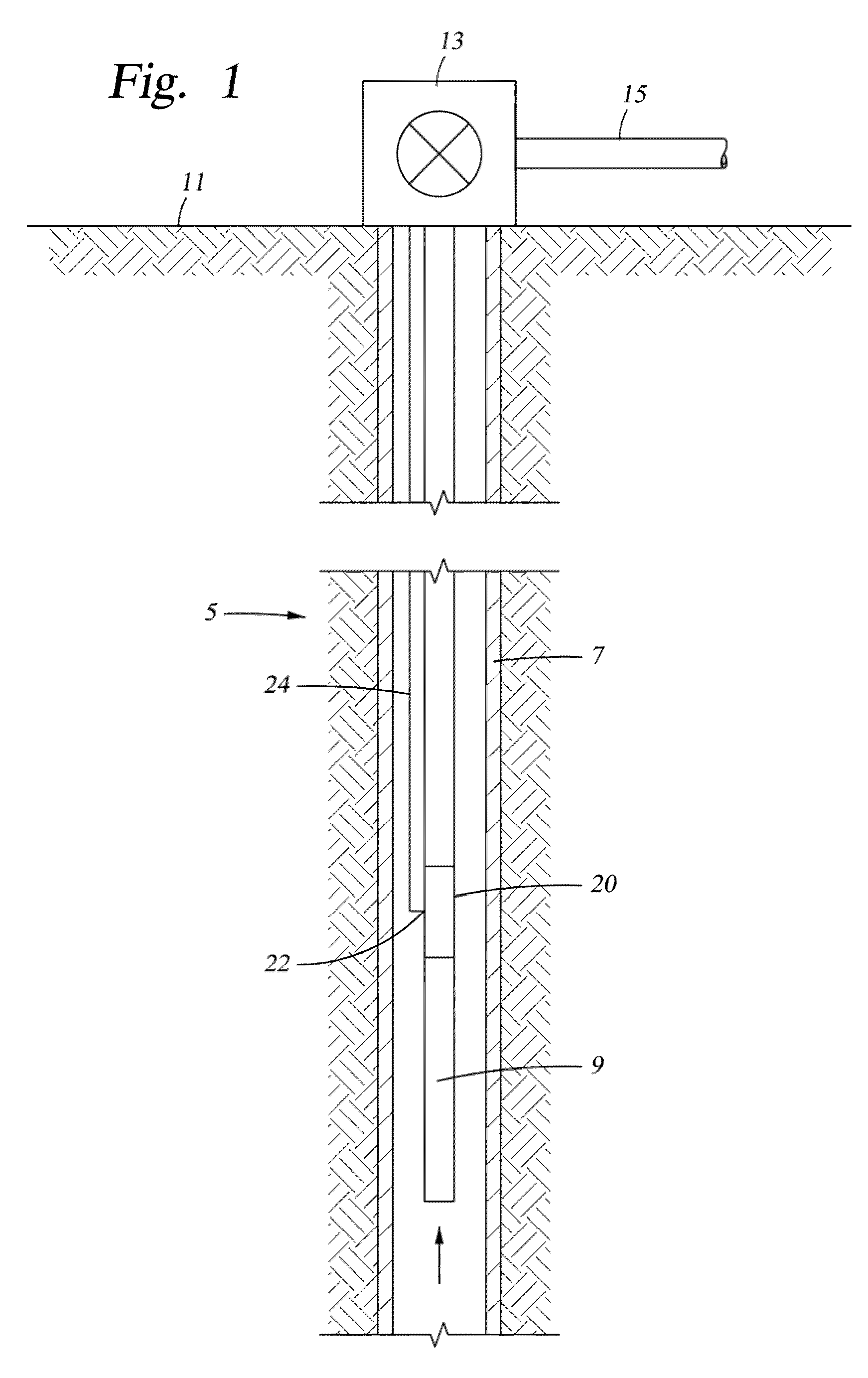
FIELD OF THE INVENTION[0001]This invention relates in general to wellbore fluid production and more specifically to a method of measuring multiphase fluid flow using a two stage flow meter.BACKGROUND OF THE INVENTION[0002]Flowmeters are often used for measuring flow of fluid produced from hydrocarbon producing wellbore. The flowmeter may be deployed down hole within a producing wellbore, a jumper or caisson used in conjunction with a subsea wellbore, or a production transmission line used in distributing the produced fluids. Monitoring fluid produced from a wellbore is useful in wellbore evaluation and to project production life of a well. In some instances transmission lines may include fluid produced from wells having different owners. Therefore proper accounting requires a flow measuring device that monitors the flow contribution from each owner.[0003]The produced fluid may include water and / or gas mixed with liquid hydrocarbon. Knowing the water fraction is desirable to ensure a...

Claims


Application Information

Patent Timeline
Patent Type & Authority Patents(United States)
IPC IPC(8): G01F1/74
CPCG01F1/74G01F1/36
Inventor ONG, JOO
Owner BAKER HUGHES INC
Learn More