
Interactive debugging system with debug data base system

The debugging system addresses the inflexibility of modern debuggers by using a debug database to manage information, allowing multiple interfaces and enabling remote debugging through a Web browser interface, thus improving analysis capabilities and usability.

Inactive Publication Date: 2010-04-27
GEN DIGITAL INC
View PDF21 Cites 25 Cited by
  • Summary
  • Abstract
  • Description
  • Claims
  • Application Information

AI Technical Summary

Benefits of technology

This solution allows for flexible user interfaces, including Web browser integration, enabling remote debugging and efficient analysis of past program executions without affecting the debugging source or interface, enhancing the usability and versatility of debuggers.

Problems solved by technology

Problems with this arrangement include first, that the interactive user interface can only be used to analyze the current execution of the program; information about past executions is contained in the log file, and that requires other tools to read it.
A second problem is that the proprietary user interface requires that the user interacting with the debugger have the interface software and also limits the user to the kind of interaction dictated by the proprietary user interface.
One consequence of the use of proprietary user interfaces is that debuggers have not taken advantage of the standard graphical user interfaces that have lately evolved.
In particular, they have not been adapted to work with Web browsers, and that in turn means not only that the programmer must use a less-convenient user interface than that provided by the his or her Web browser, but also that a progranmer who wants to debug a program that is running on a remote machine cannot use the Web browser and the Internet to do the debugging, but must instead have a special connection to the remote machine which permits the programmer to use the proprietary interface.

Method used


Image

  • Interactive debugging system with debug data base system
  • Interactive debugging system with debug data base system
  • Interactive debugging system with debug data base system

Examples


Embodiment Construction

[0026]The following Detailed Description will first present an overview of a debugging system that includes the invention, will then show how the invention may be used to provide multiple user interfaces, including a Web browser user interface, for an existing debugging system, and will then present details of the debug database and the Web browser interface in a preferred embodiment. The source of the debugging information in a preferred embodiment is an automatic memory management system, and the Detailed Description also includes details of the automatic memory management system.

Overview of a Debugging System Constructed According to the Invention:

[0027]FIG. 1

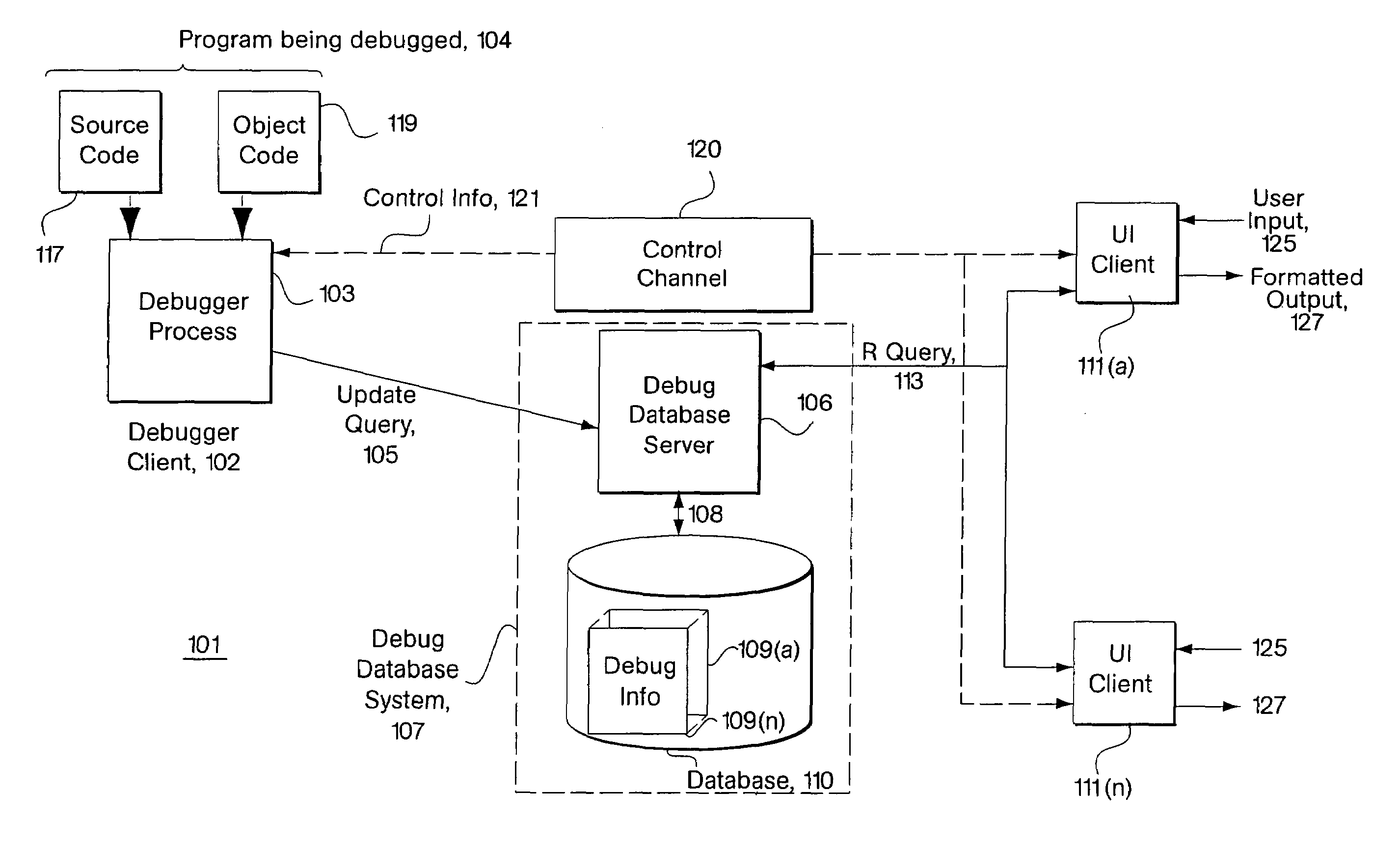
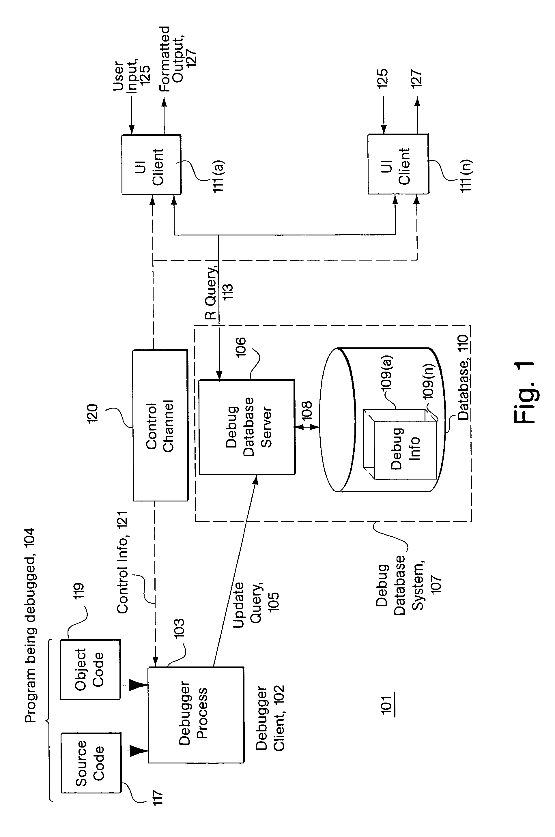
[0028]FIG. 1 is a conceptual block diagram of a debugging system 101 that is constructed according to the invention. The major components of debugging system 101 are debugging data base system 107, debugger client 102, and one or more user interface (UI) clients 111. Debugging data base system 107 contains a database 110 wit...


PUM


Abstract

An interactive system for debugging programs in which a persistent data base system responds to update queries containing debugging information from a debugging information source and to read queries on the debugging information from an interactive interface. The interactive interface produces the read queries in response to inputs from users and formats the results of the read queries as required by the user. One source of inputs is a standard Web browser for which the interactive interface functions as a Web server. The system also includes a command channel by which the source of debugging information receives commands from the interactive interface. In one embodiment, the command channel is implemented in the data base. In a disclosed implementation, the source of debugging information provides memory debugging information. Also disclosed are techniques for using an automatic memory management system to reduce memory fragmentation and heap footprint size.

Description

CROSS REFERENCES TO RELATED APPLICATIONS[0001]The present application is a continuation of U.S. patent application Ser. No. 09 / 529,760, filed Apr. 18, 2000, now U.S. Pat. No. 6,938,245, which is the national stage under 35 U.S.C. § 371 of PCT application number PCT / US98 / 22923, filed Oct. 28, 1998, which claims benefit of priority to the provisional application U.S. Ser. No. 60 / 063,992, Michael Spertus, Debugger with web browser interface, filed Oct. 29, 1997.BACKGROUND OF THE INVENTION[0002]1. Field of the Invention[0003]The invention concerns interactive programming tools generally and more specifically concerns interactive program debuggers.[0004]2. Description of the Prior Art[0005]Debuggers are tools used by programmers to determine what is going on when a program is executed. A debugger typically permits a programmer to start and stop the program's execution and to examine the state of the memory (including hardware registers) being used by the program. Modern debuggers are int...

Claims


Application Information

Patent Timeline
Patent Type & Authority Patents(United States)
IPC IPC(8): G06F9/44G06F11/36
CPCG06F11/3664G06F12/0253
Inventor SPERTUS, MICHAEL P.FITERMAN, CHARLESRODRIGUEZ RIVERA, GUSTAVO
Owner GEN DIGITAL INC
Learn More