
Wavelength reconfigurable optical network

a technology of optical networks and reconfigurable optical networks, applied in the field of optical networks, can solve the problems of limiting the flexibility of wavelength assignment in the metro ring network, the possibility of wavelength reconfiguration and re-use, and the cost of current pon architectures

Active Publication Date: 2010-04-27
UNIVERSITY OF OTTAWA
View PDF6 Cites 28 Cited by
  • Summary
  • Abstract
  • Description
  • Claims
  • Application Information

AI Technical Summary

Benefits of technology

"The invention provides a wavelength reconfigurable optical network for providing communication services to end-users. The network includes a metro ring network and a first passive optical network connected at one of the network nodes. The first PON includes optical network units associated with the end-users and a remote node for directing wavelength channels to the ONUs through optical access links. The MRN includes a metro hub for aggregating communication signals onto wavelength channels and a first OADM for selectively dropping wavelength channels. The ONUs include optical receivers with tunable optical filters and colorless transmitters. The technical effects of the invention include wavelength reconfiguration, shared resources, and improved bandwidth sharing."

Problems solved by technology

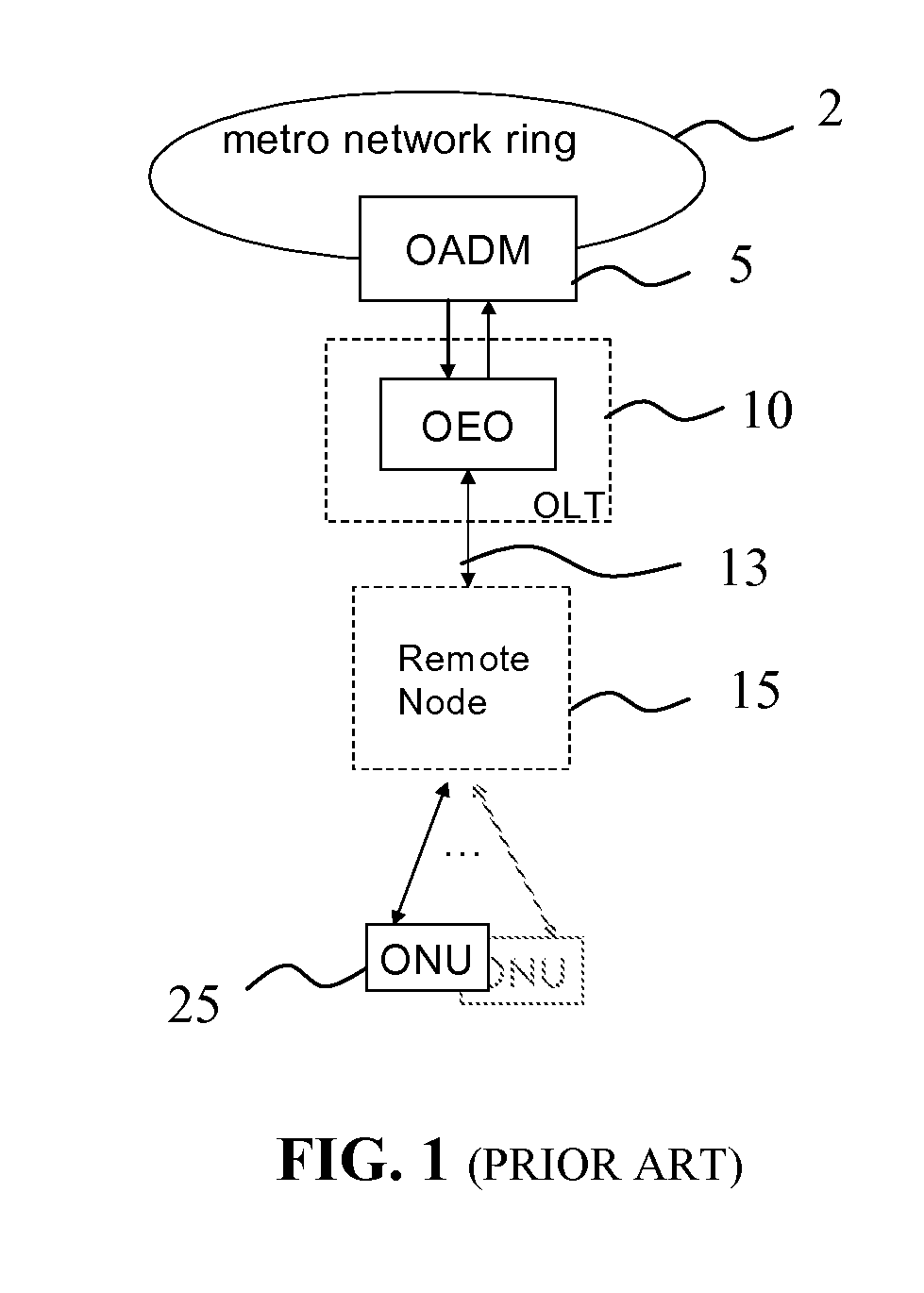
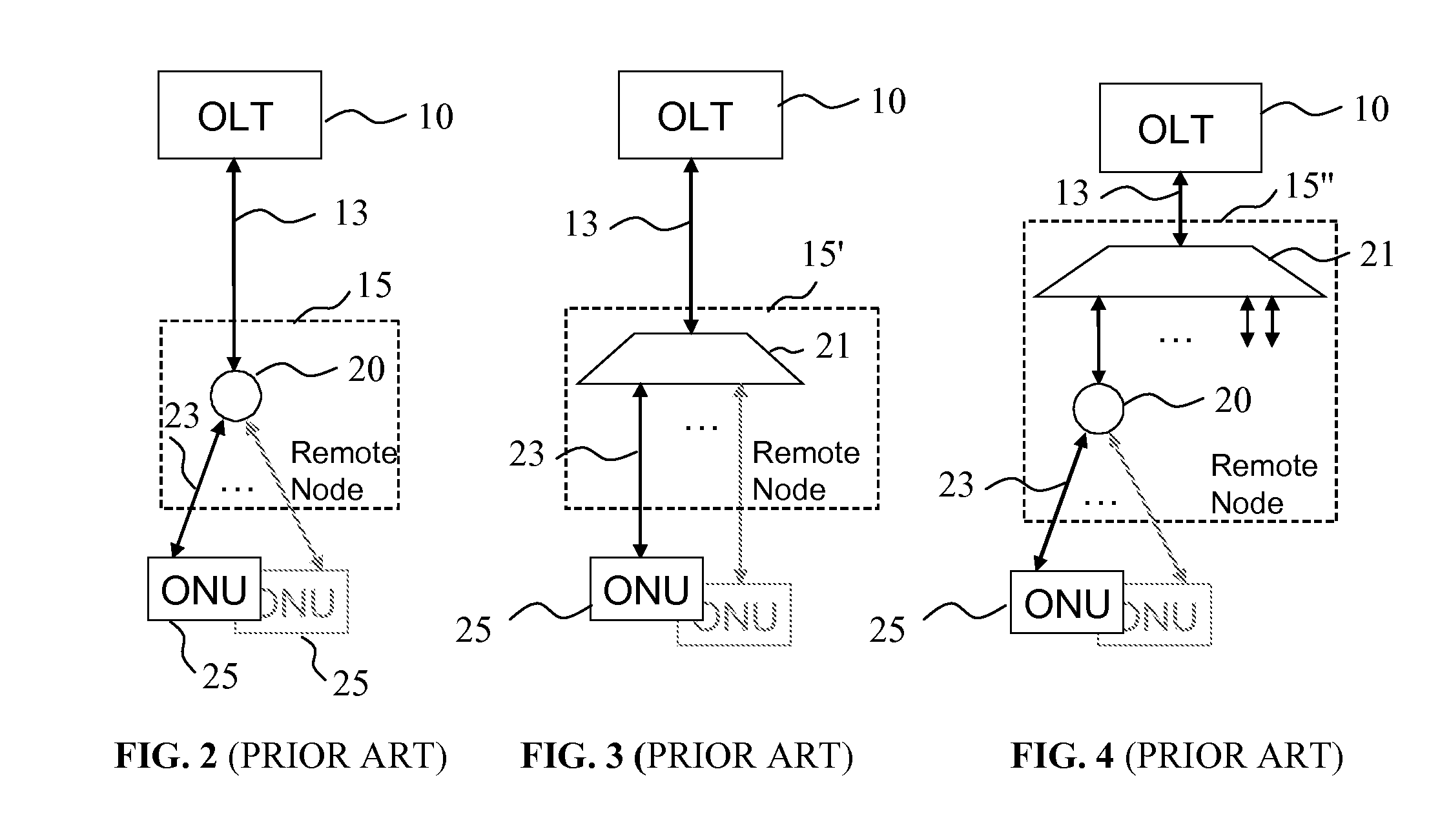
One drawback of the aforedescribed prior-art PON architectures is that they require OEO conversion at each OLT, wherein an OLT receives an optical signal coming from the metro ring network 2, and re-transmits as downstream traffic using one or several dedicated fixed optical transmitters; disadvantageously, the OLT represents a significant part of the cost of current PON architectures.
Another drawback of the prior art access network architectures in that the metro edge node 5, which serves as an interface between the metro ring network and the PON, typically utilizes a fixed optical add-drop multiplexer (OADM), so that wavelengths that are added and dropped at each metro edge node are fixed.
This disadvantageously limits the flexibility of wavelength assignment in the metro ring network and possibilities for wavelength reconfiguration and re-use.

Method used


Image

  • Wavelength reconfigurable optical network
  • Wavelength reconfigurable optical network
  • Wavelength reconfigurable optical network

Examples


numerical example

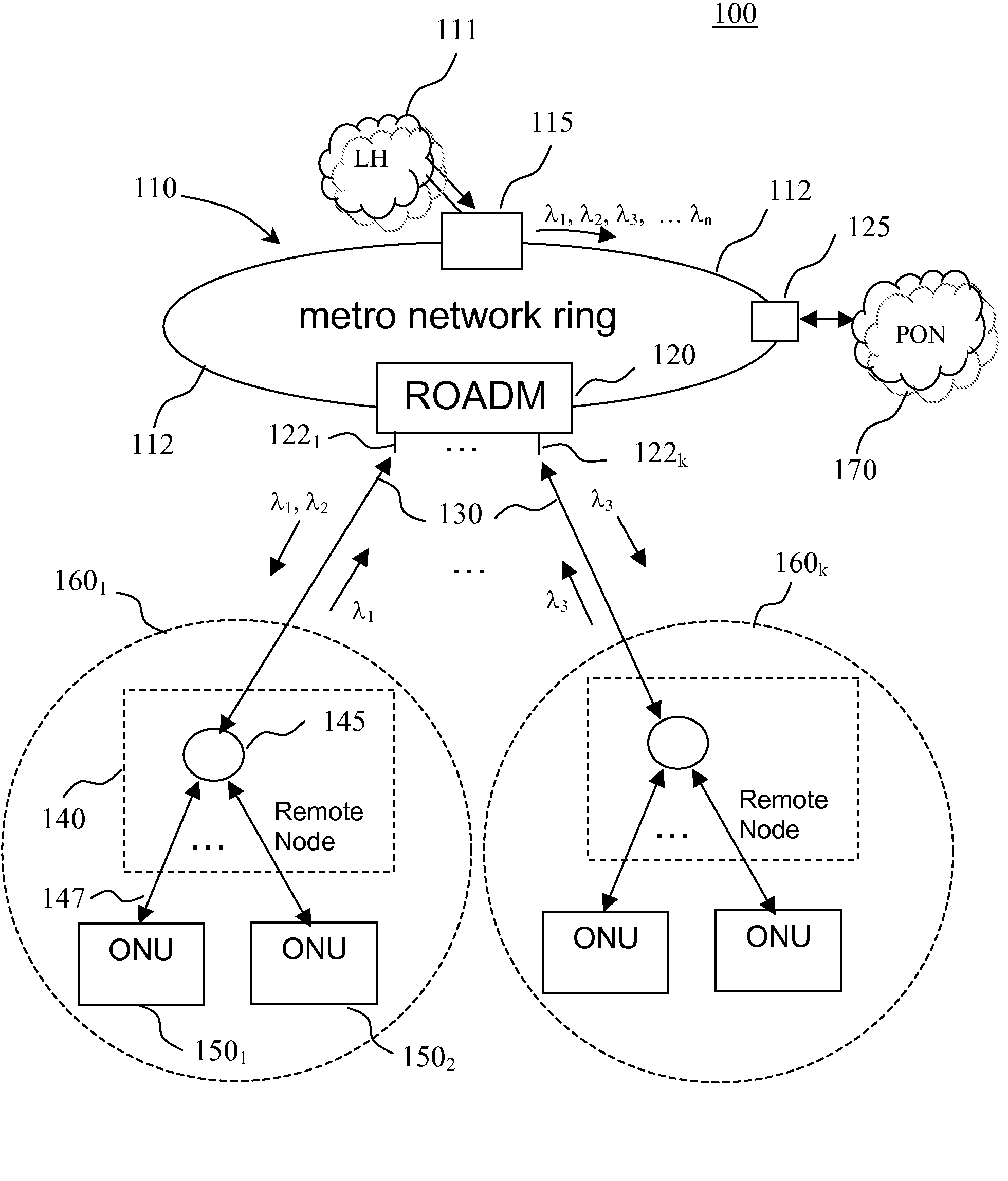
[0063]By way of example, the optical network of FIG. 5 has the following parameters: the length of optical fiber link between the metro hub 115 and the ROADM 120 is 10 km, the length of the trunk optical link 135 is 10 km, output power of the metro-hub transmitters is 5 dBm, output power of the ONU transmitters 3 dBm; insertion loss of optical devices in the wavelength path between the ONU transmitter / receiver and the metro hub transmitter / receiver: AWG 315—3 dB, circulator—1 dB, optical fiber loss—0.25 dB / km, ROADM—5 dB, optical splitter at the remote node 140—12 dB corresponding to 1×16 splitter, ONU optical coupler—3 dB, tunable filter—1 dB. This corresponds to a typical value of the overall optical loss associated with a wavelength path between the metro hub 115 and an ONU 150 of about 30 dB, so that the ONU transmitter and the ONU receiver each receive a downstream optical signal of about −25 dBm, while optical power of the upstream wavelength channel received by a metro hub re...


PUM


Abstract

The invention provides a unified optical network architecture for metro and access communication networks, wherein a metro ring network interfaces access PONs through one or more reconfigurable Optical Add / Drop Multiplexers to provide wavelength-reconfigurable all-optical transmission of communication signals from the metro ring network to designated optical network units associated with the end-users, and wherein one metro hub located in the metro ring network is utilized to set transmission wavelengths and timing for both downstream and upstream signal transmission for multiple access PONs.

Description

CROSS-REFERENCE TO RELATED APPLICATIONS[0001]The present invention claims priority from U.S. Provisional Patent Application No. 60 / 807,507 filed Jul. 17, 2006, entitled “Optical Access Network Architecture”, which is incorporated herein by reference.TECHNICAL FIELD[0002]The present invention relates generally to optical networks, and in particular to wavelength reconfigurable optical networks utilizing reconfigurable optical add-drop multiplexers as interfaces between a metro ring network and access passive optical networks for providing wavelength-based services to end users.BACKGROUND OF THE INVENTION[0003]A typical metro-area network aggregates access traffic over a ring roughly 40-50 km in circumference, with typically 4-5 nodes interspersed along it. Each node serves as a portal for a local community through an access network, with residential and business users being added over time. Broadband access networks based on so called fiber to the home (FTTH), fiber to the curb (FTTC...

Claims


Application Information

Patent Timeline
Patent Type & Authority Patents(United States)
IPC IPC(8): H04J14/00H04J14/02
CPCH04J14/0212H04J14/0216H04J14/0226H04J14/0286H04J14/0246H04J14/0247H04J14/025H04J14/0252H04J14/02H04J14/0227H04J14/0282H04J2014/0253H04J14/0283
Inventor BOUDREAULT, FRANCOISANIS, HANANPRAMOD, S. RICHARD
Owner UNIVERSITY OF OTTAWA
Learn More