
Oil baffle for gas turbine fan drive gear system

a technology for gas turbine fans and gear systems, applied in the direction of gearing details, machines/engines, mechanical apparatuses, etc., can solve the problems of increasing cost, complicated assembly, and multiple components of arrangement, and increasing complexity

Active Publication Date: 2010-04-27
RTX CORP
View PDF9 Cites 198 Cited by
  • Summary
  • Abstract
  • Description
  • Claims
  • Application Information

AI Technical Summary

Problems solved by technology

Prior art carrier arrangements have required multiple components and complicated assembly in order to accommodate the oil baffles.
Furthermore, separate oil spray bars and oil baffles complicate assembly and increase cost.

Method used


Image

  • Oil baffle for gas turbine fan drive gear system
  • Oil baffle for gas turbine fan drive gear system
  • Oil baffle for gas turbine fan drive gear system

Examples


Embodiment Construction

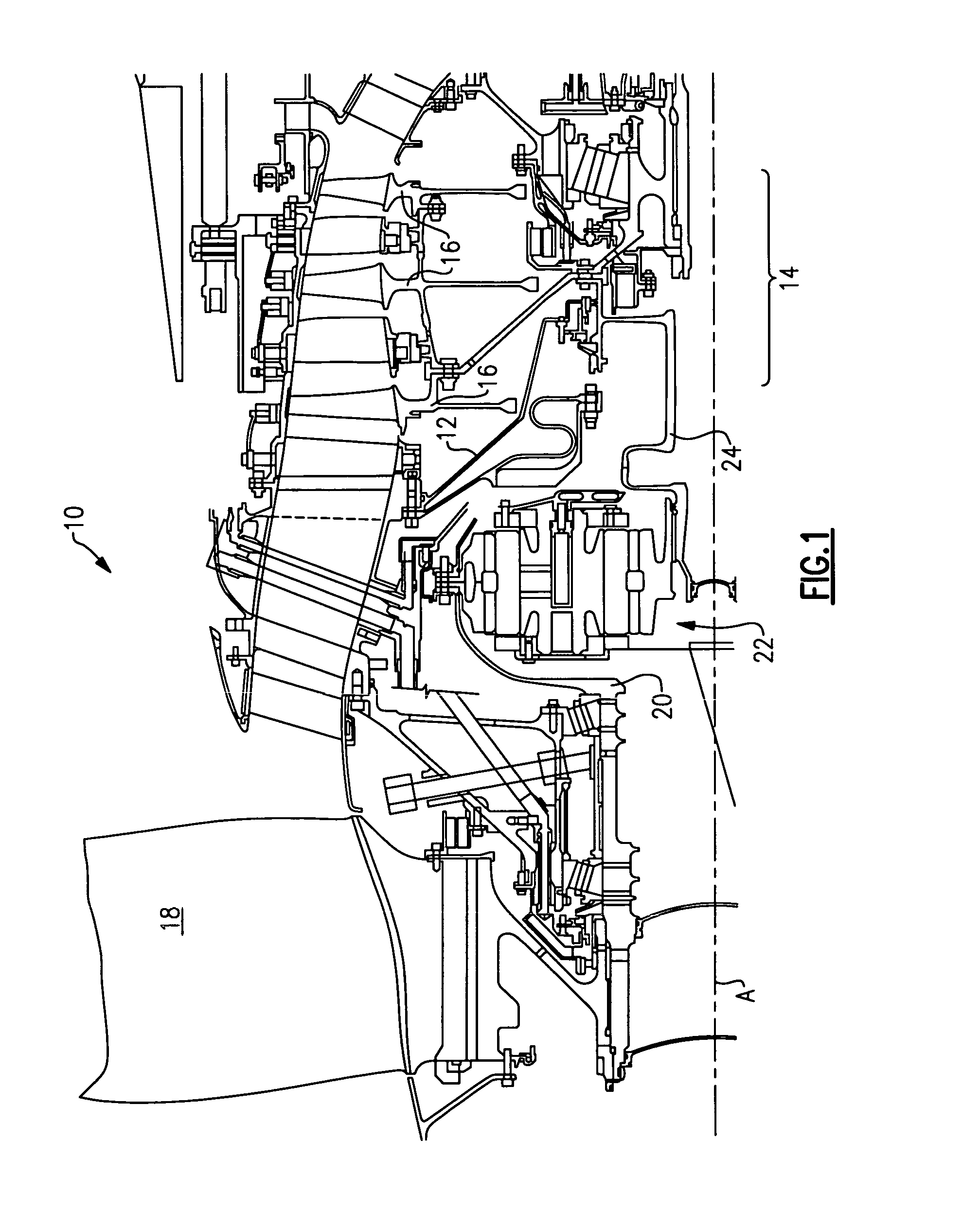
[0012]A portion of a gas turbine engine 10 is shown schematically in FIG. 1. The turbine engine 10 includes a fixed housing 12 that is constructed from numerous pieces secured to one another. A compressor section 14 having compressor hubs 16 with blades are driven by a turbine shaft (not shown) about an axis A. A turbo fan 18 is supported on a turbo fan shaft 20 that is driven by a compressor shaft 24, which supports the compressor hubs 16, through an epicyclic gear train 22.

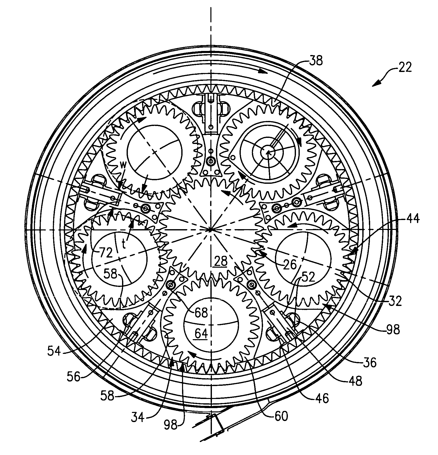
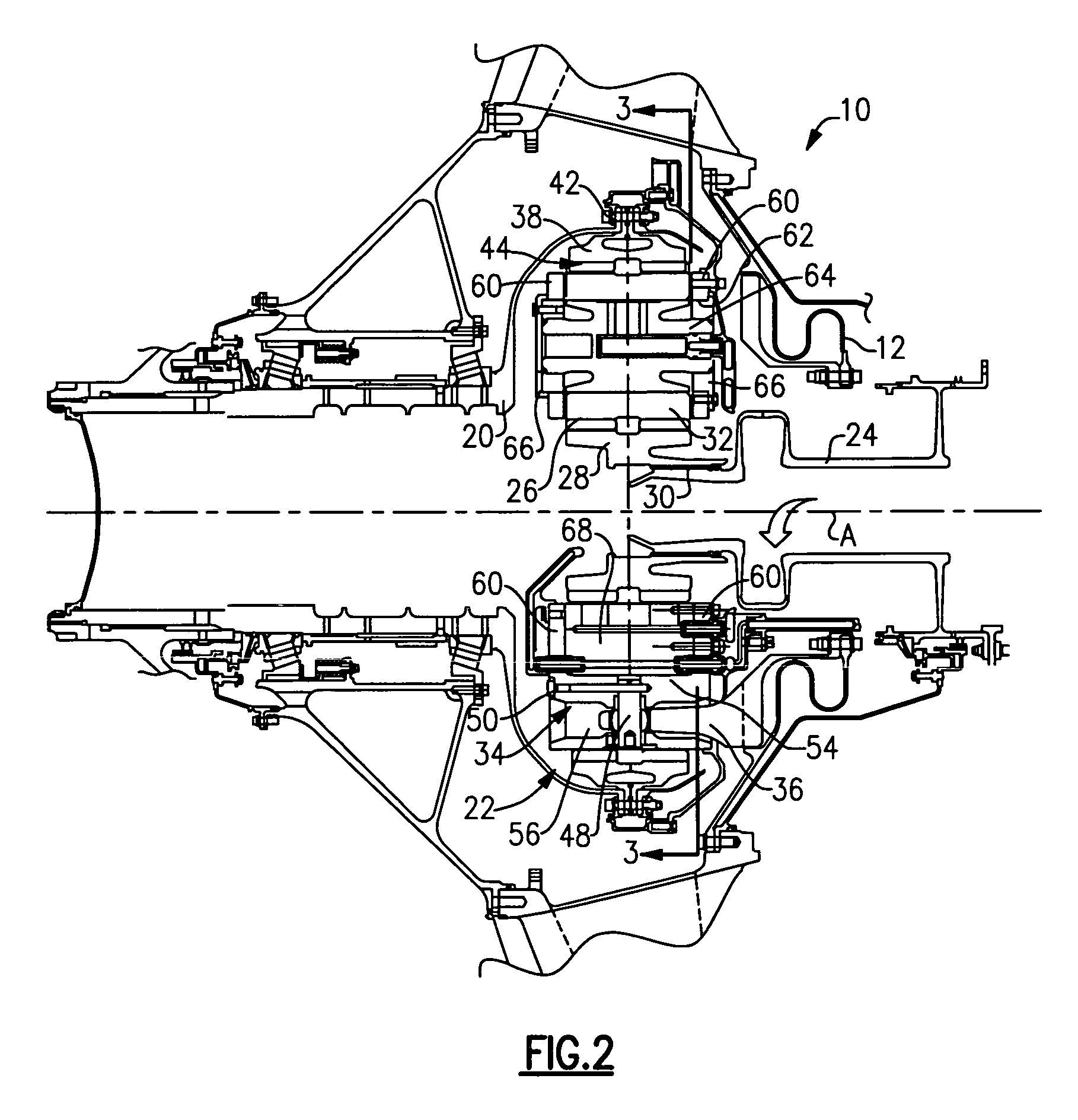
[0013]In the example arrangement shown, the epicyclic gear train 22 is a star gear train. Of course, the claimed invention also applies to other epicyclic gear trains such as a planetary arrangement. Referring to FIG. 2, the epicyclic gear train 22 includes a sun gear 28 that is connected to the compressor shaft 24, which provides rotational input, by a splined connection 30. A carrier 34 is fixed to the housing 12 by a torque frame 36. The carrier 34 supports intermediate gears (which are star gears 32 in the a...


PUM

PropertyMeasurementUnit
circumferenceaaaaaaaaaa
areaaaaaaaaaaa
outer circumferenceaaaaaaaaaa

Abstract

A gas turbine engine includes an epicyclic gear train that drives a turbo fan. The epicyclic gear train employs a one-piece carrier in which the spaced side walls are interconnected with circumferentially spaced apart mounts to form a unitary structure. Baffles are secured to the carrier near the mounts and provide lubrication passages that spray oil onto the sun gear and / or intermediate gears arranged between the baffles. The baffles can be constructed from a different material than the carrier since the baffles are not structural components in the gear train.

Description

BACKGROUND OF THE INVENTION[0001]This invention relates to an oil baffle arrangement for use in an epicyclic gear train employed to drive a turbo fan.[0002]Gas turbine engines typically employ an epicyclic gear train connected to a turbine section of the engine, which is used to drive the turbo fan. In a typical epicyclic gear train, a sun gear receives rotational input from a turbine shaft through a compressor shaft. A carrier supports intermediate gears that surround and mesh with the sun gear. A ring gear surrounds and meshes with the intermediate gears. In arrangements in which the carrier is fixed against rotation, the intermediate gears are referred to as “star” gears and the ring gear is coupled to an output shaft that supports the turbo fan. In arrangements in which the ring gear is fixed against rotation, the intermediate gears are referred to as “planetary” gears and the carrier is coupled to the output shaft that supports the turbo fan.[0003]The epicyclic gear train gears...

Claims


Application Information

Patent Timeline
Patent Type & Authority Patents(United States)
IPC IPC(8): F16H57/04
CPCF01D25/18F16H57/0421F16H57/0427F02C3/04F16H57/0423F16H57/0479F16H57/0482F02C7/36Y10T29/49323F16H57/0486F16H57/082F05D2230/60F05D2260/40311F05D2260/98Y10T29/49464Y10T29/4932Y10T29/49316F16H57/046
Inventor SHERIDAN, WILLIAM G.MCCUNE, MICHAEL E.
Owner RTX CORP
Learn More