
Automatic locking mechanism for a measuring tape device

a technology of automatic locking and tape, which is applied in the direction of measuring devices, instruments, and mechanical means, can solve the problems of inconvenient reading of tape measurement by users, too high production cost, and complicated devices, and achieves easy reading of tape measurement, simple construction, and large friction

Active Publication Date: 2010-04-27
TECHTRONIC POWER TOOLS TECHNOLOGY LTD
View PDF11 Cites 18 Cited by
  • Summary
  • Abstract
  • Description
  • Claims
  • Application Information

AI Technical Summary

Benefits of technology

"The present invention is a measuring tape device with a simple structure and a more reliable locking mechanism. The device includes a casing containing a coilable tape, a bobbin connected to the casing with a spring, and a stopper positioned inside the casing. The stopper has an end connected to an actuator by a linkage part, and an elastic piece fixes the stopper inside the casing. The device also includes a frictional piece to generate large friction between the stopper and the tape to lock the tape in place. The invention is advantageous in its simple construction and reduced production cost."

Problems solved by technology

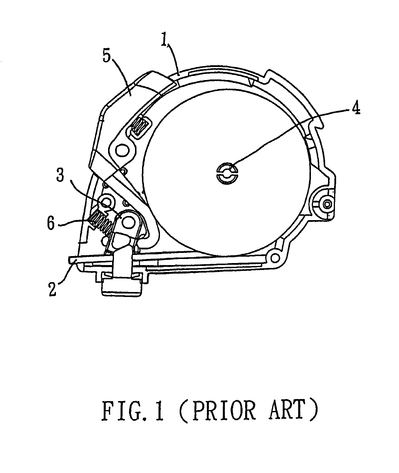
This type of measuring tape device does not have a locking mechanism, when a user release the distal end of the tape after the tape is extracted out of the casing, the tape is immediately retracted back into the casing, so it is inconvenient for the user to read the measurement on the tape.
However, this kind of measuring tape device consists of too many components, so the structure of the device becomes too complicated, and the production cost becomes too high.
Furthermore, since the locking mechanism of the measuring tape depends on the “J” shape extension piece at the front end of button 5 to move the stopper 3, if the contact between the “J” shape extension piece and the stopper 3 deteriorates due to extensive usage, the effectiveness of the locking mechanism of the measuring tape will be affected, which decreases the reliability of the locking mechanism.

Method used


Image

  • Automatic locking mechanism for a measuring tape device
  • Automatic locking mechanism for a measuring tape device
  • Automatic locking mechanism for a measuring tape device

Examples


Embodiment Construction

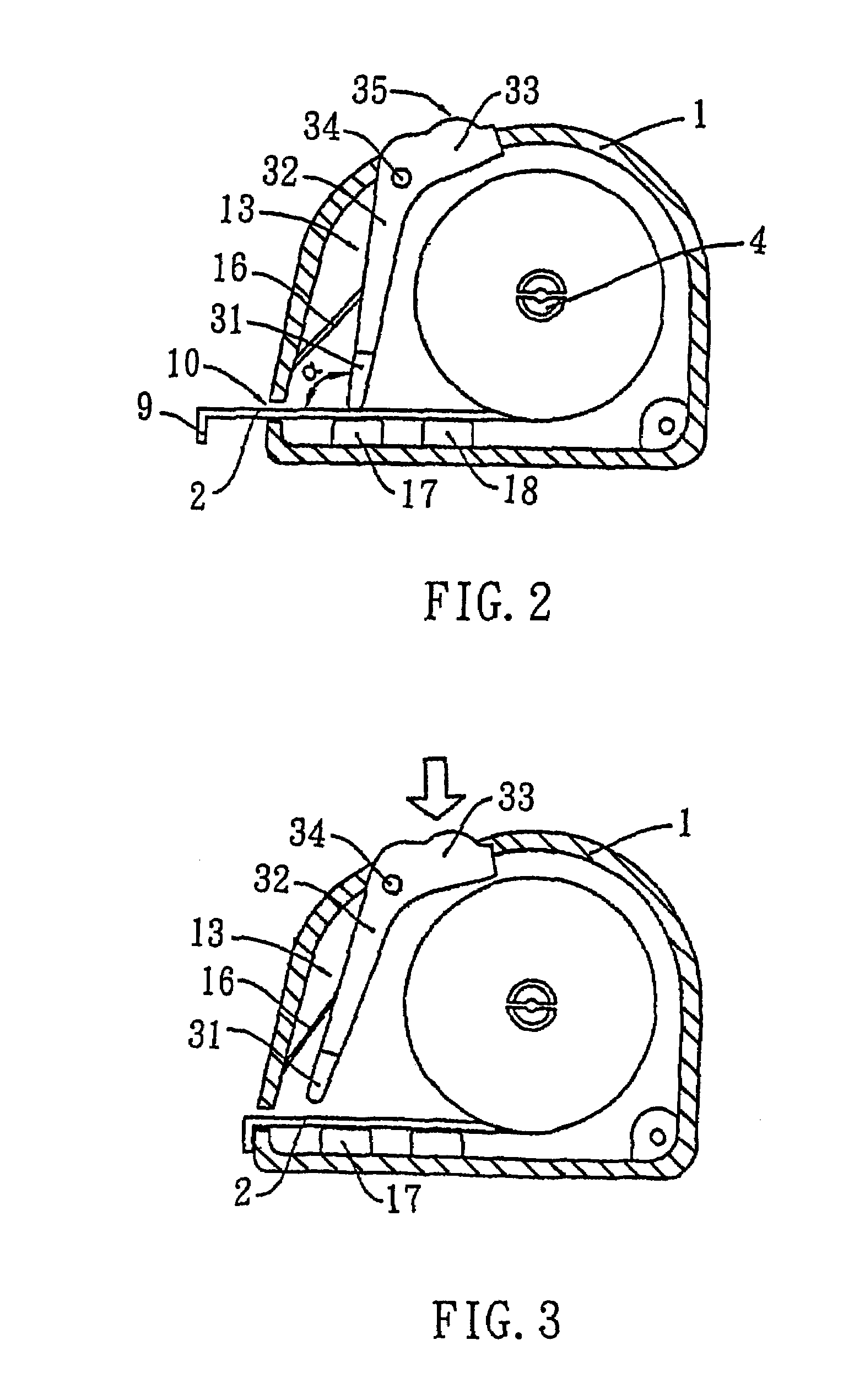
[0016]In reference to FIG. 2, it is a demonstrative view showing the embodiment of the construction of measuring tape device of present invention. The measuring tape device of the embodiment of the present invention comprises of a casing 1, there is a bobbin 4 located at the center part of the casing 1, and the bobbin 4 is attached to casing 1 by a loaded spring. Inside the casing 1 there is also a coilable tape 2, one end of the tape 2 is connected to the spring (not shown) and the tape is wound around the bobbin 4. The other end of the tape 2 is extended outside through the aperture 10 that is formed on the lower end of casing 1, and this end of the tape is also connected to a hook member 9. The section of the tape 2 positioned between the coilable tape and the hook member 9 is the linear portion of tape 2, it is located near the bottom of to casing 1.

[0017]The automatic locking mechanism of present invention is applied with a stopper 13, the stopper 13 comprises of an end piece 3...


PUM


Abstract

A measuring tape device with automatic locking mechanism comprises of a casing, a bobbin that is set within the casing with a spring, a coilable tape that is contained in the casing. One end of the tape is connected to the spring and is wound around the bobbin, while the other end is extended outside through an aperture that is formed at the lower end to of casing, and this other end is connected to a hook member. The device also comprises of a stopper, it consists of an end that is positioned on the linear portion of tape, and an actuator that is connected to the end portion by a linkage part. The actuator is extruded outside and is settled at the surface of the casing. The device includes a hinge joint for fixating the stopper inside the casing and for allowing the stopper to rotate, and an elastic member placed between the casing and the linkage portion. The measuring tape device of present invention will lock the tape in place after the tape is extracted out from the casing, the locking mechanism of the tape is considered effective, and it has relatively low production cost, hence it is beneficial for mass production.

Description

BACKGROUND OF THE INVENTION[0001]1. Field of the Invention[0002]The present invention relates to a measuring tape device, in particular, it refers to a measuring tape device that has an automatic locking to mechanism.[0003]2. Description of Prior Art[0004]With the increasing demand for surveying, the measuring tape devices get to be more widely used. An early conventional measuring tape device comprises of a casing, there is a coilable tape contained inside the casing. At the center of the casing is a bobbin, one end of the tape is connected to the bobbin with a spring, and the other end of the tape extends out of the casing through an aperture. This type of measuring tape device does not have a locking mechanism, when a user release the distal end of the tape after the tape is extracted out of the casing, the tape is immediately retracted back into the casing, so it is inconvenient for the user to read the measurement on the tape.[0005]According to Chinese Patent Publication (No. C...

Claims


Application Information

Patent Timeline
Patent Type & Authority Patents(United States)
IPC IPC(8): G01B3/10
CPCG01B3/1005G01B2003/1038G01B2003/1015
Inventor HUANG, JASON
Owner TECHTRONIC POWER TOOLS TECHNOLOGY LTD
Learn More