
Guide clamp for guiding placement of a guide wire in a femur

a technology for guiding wires and femurs, applied in the field of guides for guiding wire placement in orthopedic surgery, can solve problems such as difficult handling of subsequent hip joint problems, and achieve the effect of accurate centering of guide pins

Inactive Publication Date: 2010-04-20
MICROPORT ORTHOPEDICS HLDG INC
View PDF29 Cites 180 Cited by
  • Summary
  • Abstract
  • Description
  • Claims
  • Application Information

AI Technical Summary

Benefits of technology

Enables precise and efficient placement of guide wires, facilitating improved accuracy and reduced operational complexity in femoral head resurfacing surgeries, with the ability to adjust the angle of the guide wire for optimal prosthesis alignment.

Problems solved by technology

When severe hip joint problems are encountered, it is sometimes necessary to replace a portion of the hip joint; either the ball or the socket or both.
However, this “total” hip replacement technique was drastic, involving complete removal of the head and neck of the femur, and made any subsequent hip joint problems difficult to handle.

Method used


Image

  • Guide clamp for guiding placement of a guide wire in a femur
  • Guide clamp for guiding placement of a guide wire in a femur
  • Guide clamp for guiding placement of a guide wire in a femur

Examples


Embodiment Construction

[0037]The present invention now will be described more fully hereinafter with reference to the accompanying drawings, in which some, but not all embodiments of the invention are shown. Indeed, this invention may be embodied in many different forms and should not be construed as limited to the embodiments set forth herein; rather, these embodiments are provided so that this disclosure will satisfy applicable legal requirements. Like numbers refer to like elements throughout.

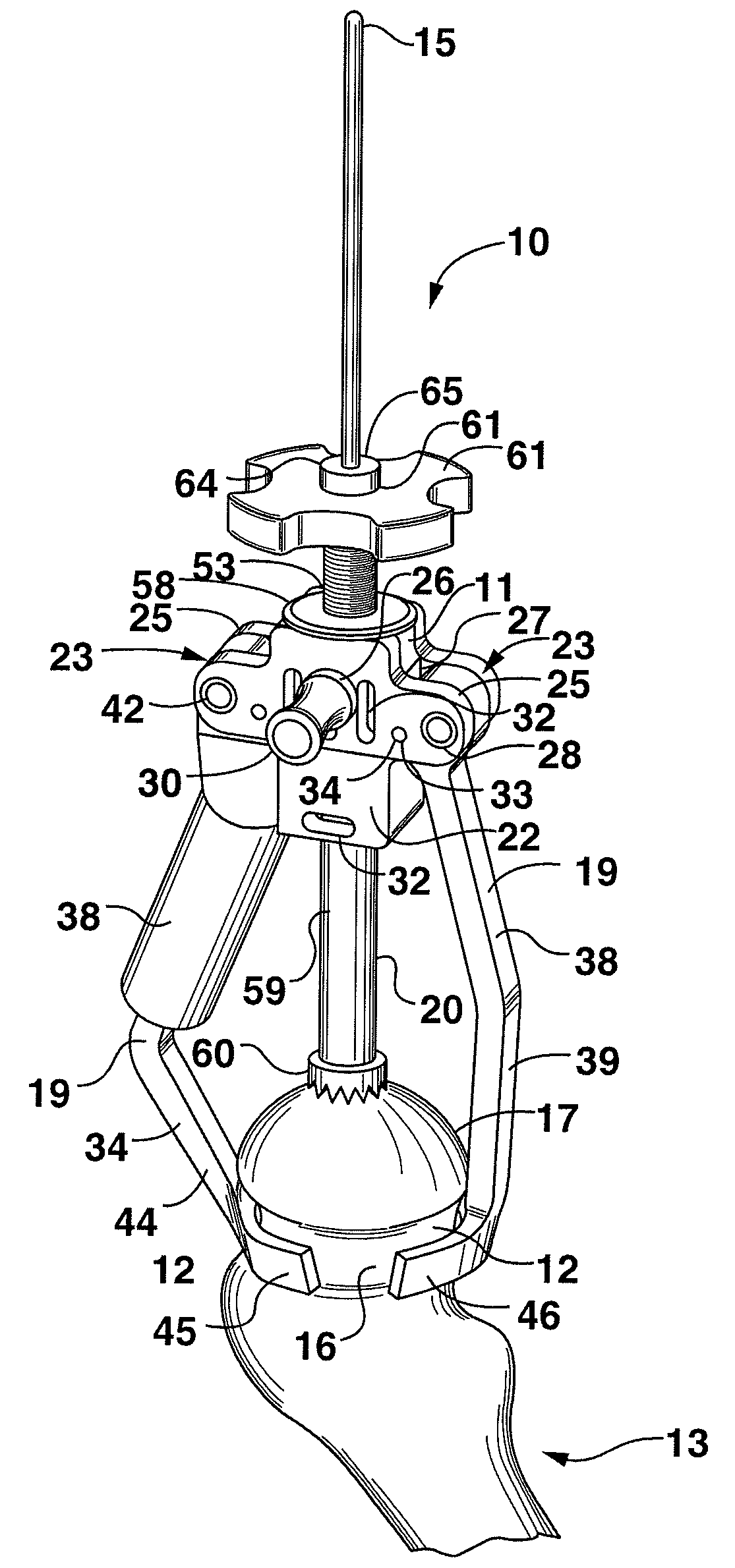
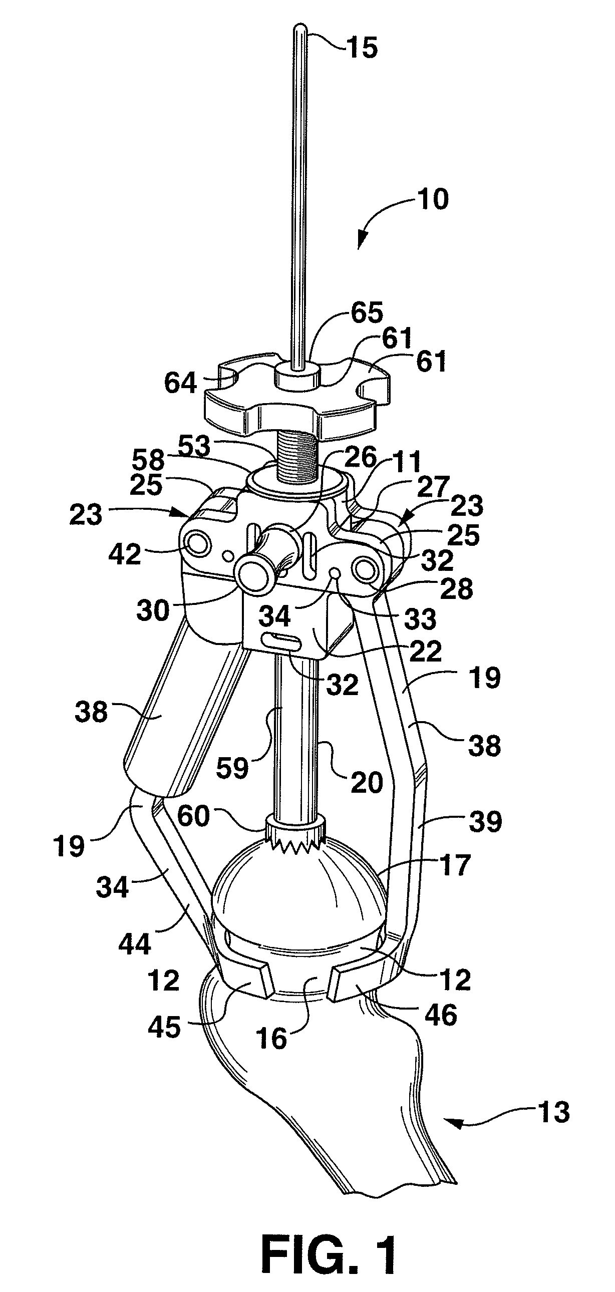
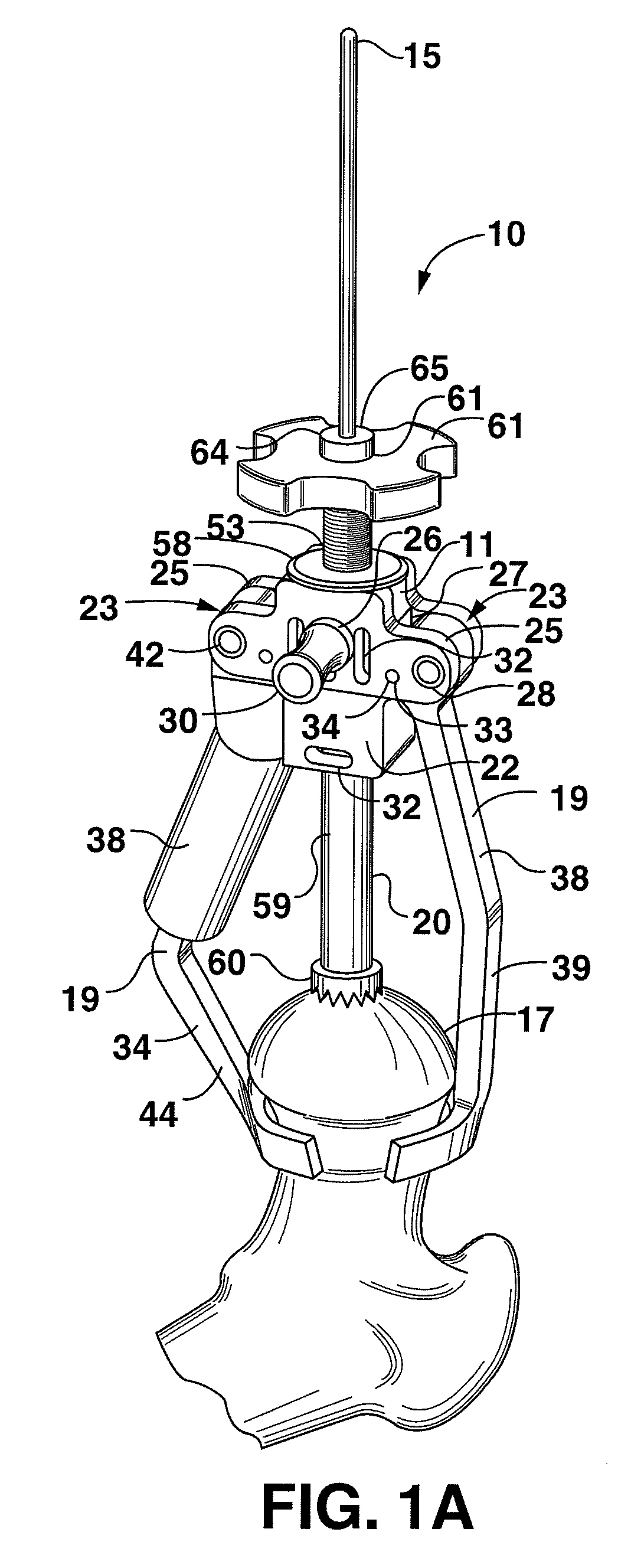
[0038]A guide clamp 10 of one embodiment of the present invention includes a body 11 movably supporting two or more clamping surfaces 12 that can be moved from an open (separated) position that allows insertion of a femur 13 (and more specifically the femoral head 17) therebetween and a closed position wherein the clamping surfaces are firmly secured about the femur (e.g., around a neck 16 of the femur), as shown in FIGS. 1-3. Defined in the body 11 is a guide opening 14 that allows passage of a primary guide shaf...


PUM


Abstract

A guide clamp for clamping a femur and guiding placement of a guide wire relative to the femur. The guide clamp includes a body supporting a pair of clamping surfaces at the end of a pair of clamping arms that are spring-biased to move with respect to each other into a closed position to grip the femur. Defined by the body is a guide opening that guides insertion of the guide pin once the femur has been gripped. One of the clamping arms of the guide clamp may have proximal and distal portions that are slidably adjustable with respect to each other to allow a controlled repositioning of the guide opening with respect to the femur. The guide clamp may also include an engagement member which is supported by the body of the clamp and is capable of advancing into abutting contact with the head of the femur.

Description

CROSS REFERENCE TO RELATED APPLICATIONS[0001]This application claims priority to Provisional Patent Application Ser. No. 60 / 523,799, filed Nov. 20, 2003, which is pending.BACKGROUND OF THE INVENTION[0002]1. Field of the Invention[0003]The present invention is related to the use of guides for placement of guide wires in orthopedic surgery, and more particularly to the use of a guide clamp for placement of a guide wire during femoral head resurfacing surgery.[0004]2. Description of Related Art[0005]When severe hip joint problems are encountered, it is sometimes necessary to replace a portion of the hip joint; either the ball or the socket or both. One generally used hip joint replacement technique involved removal of a head and neck of the femur, and the insertion of a long angled and tapered metal prosthesis into the central “intramedulary” canal at the open upper end of the main straight portion of the femur. This femoral prosthesis typically had a relatively small metal ball at its...

Claims


Application Information

Patent Timeline
Patent Type & Authority Patents(United States)
IPC IPC(8): A61B17/56A61B17/16A61B17/17
CPCA61B17/1668A61B17/175A61B2017/1778A61B17/1684A61B17/1778
Inventor SHELDON, MICHAEL B.LUNA, RAMONSEYER, STEVEN F.KREHLIK, BRIAN
Owner MICROPORT ORTHOPEDICS HLDG INC
Learn More