
Driving circuit, display device, and driving method for the display device

a display device and driving circuit technology, applied in the direction of electric digital data processing, instruments, computing, etc., can solve the problems of short circuiting every data line group, etc., to suppress heat generation, suppress display characteristics, and save power consumption

Active Publication Date: 2010-04-13
RENESAS ELECTRONICS CORP
View PDF6 Cites 4 Cited by
  • Summary
  • Abstract
  • Description
  • Claims
  • Application Information

AI Technical Summary

Benefits of technology

The solution enables rapid setting of data line voltages to intermediate levels, reducing power consumption and heat generation while maintaining display quality by averaging voltage values between data line groups.

Problems solved by technology

Furthermore, short-circuiting occurs every data line group.

Method used


Image

  • Driving circuit, display device, and driving method for the display device
  • Driving circuit, display device, and driving method for the display device
  • Driving circuit, display device, and driving method for the display device

Examples


first embodiment

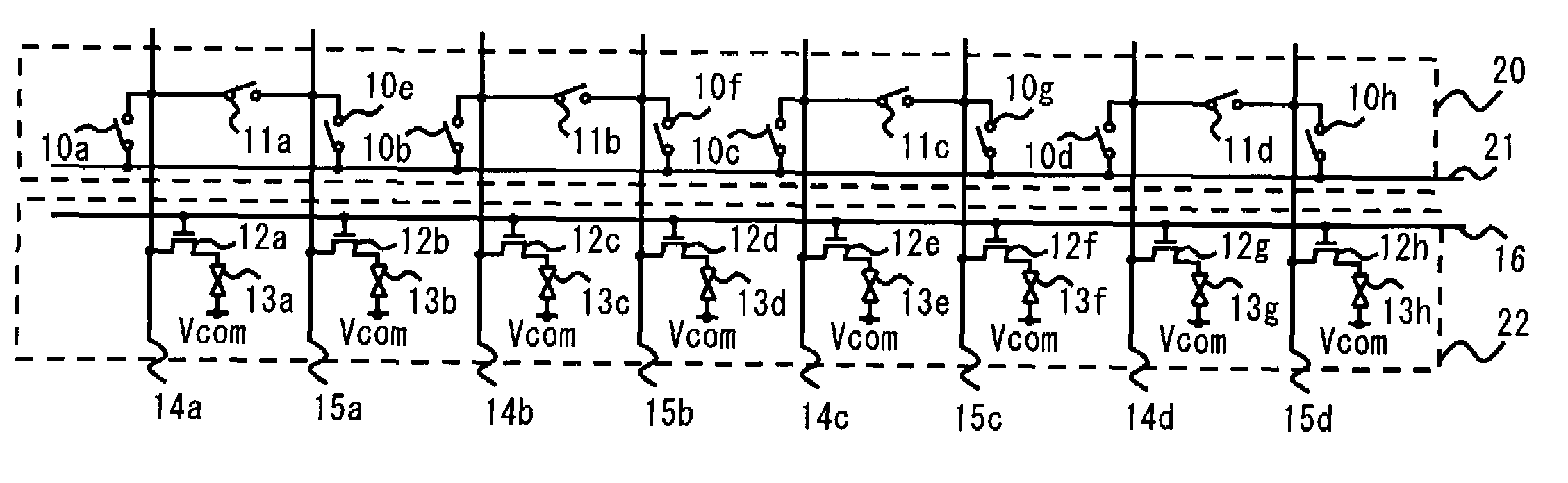
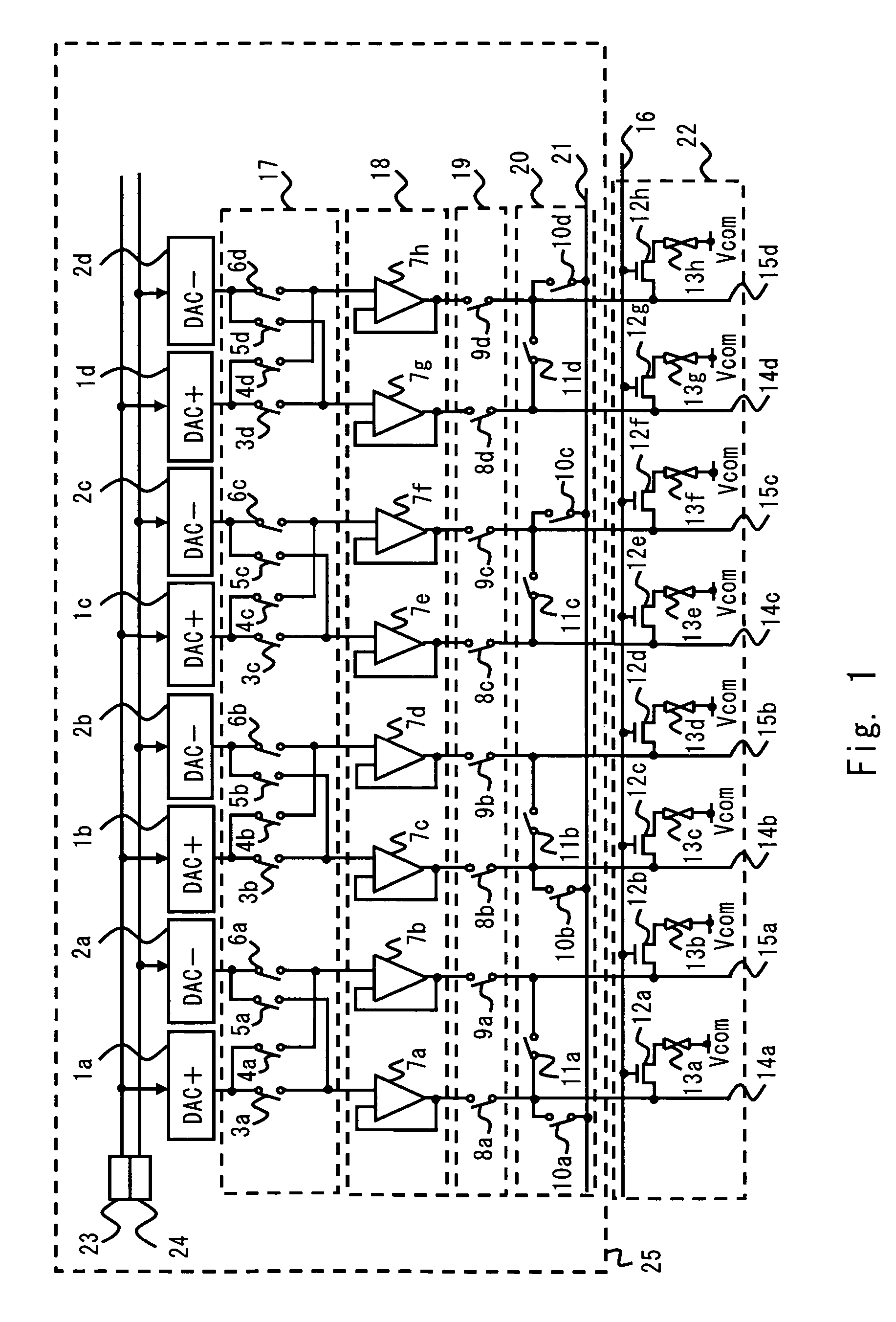
[0027]Referring to FIG. 1, a display device according to a first embodiment of the present invention is described. Here, an active matrix type liquid crystal display device is illustrated as an example of the display device. In this embodiment, a dot-inversion driving method is adopted. FIG. 1 is a schematic diagram showing the structure of a liquid crystal display device of this embodiment. The liquid crystal display device of this embodiment includes a liquid crystal panel 22 and a data line driving circuit 25. Incidentally, a scanning line driving circuit for supplying scanning signals, a backlight for applying planar light to the rear side of the liquid crystal panel 22, or the like are omitted from FIG. 1. Further for ease of illustration, FIG. 1 shows 1×8 pixels.

[0028]Incidentally, the data line driving circuit 25 may be externally connected to the liquid crystal panel 22; the circuit may be formed on a TFT array substrate connectably with all data lines.

[0029]The liquid cryst...

second embodiment

[0061]Referring to FIG. 4, a display device according to a second embodiment of the present invention is described. FIG. 4 is a schematic diagram showing the structure of the liquid crystal display device of this embodiment. The liquid crystal display device of this embodiment includes the liquid crystal panel 22 and the data line driving circuit 25. In FIG. 4, the same components as those of FIG. 1 are denoted by identical reference numerals, and repetitive description thereof is omitted here. Incidentally, in FIG. 4, a scanning line driving circuit for supplying scanning signals, a backlight for applying planar light to the rear side of the liquid crystal panel 22, or the like are omitted from FIG. 4. Further for ease of illustration, FIG. 4 shows 1×8 pixels. This embodiment differs from the first embodiment in arrangement of the buffer unit and the switching unit in the data line driving circuit 25. More specifically, the switching unit and the buffer unit are arranged in opposit...


PUM


Abstract

A driving circuit according to an embodiment of the invention includes: a switching unit for sequentially switching between a first operation of applying a positive gray-scale voltage to odd-numbered data lines and applying a negative gray-scale voltage to even-numbered data lines and a second operation of applying a negative gray-scale voltage to odd-numbered data lines and applying a positive gray-scale voltage to the even-numbered data lines; a plurality of short-circuit switches for short-circuiting a pair of adjacent odd-numbered data lines and a pair of adjacent even-numbered data lines to produce a plurality of pairs of short-circuited data lines in a switching period between the first operation and the second operation; and a plurality of common node-connected switches corresponding to the plurality of data line pairs and short-circuiting a corresponding one of the data line pairs to a common node.

Description

BACKGROUND OF THE INVENTION[0001]1. Field of the Invention[0002]The present invention relates to a driving circuit and a driving method for a display device having plural electrodes such as a liquid crystal display device, and to a display device using the same.[0003]2. Description of Related Art[0004]Along with recent development of advanced visual and information society and widespread of a multi-media system, flat display devices such as a liquid crystal display device have become more and more important. The liquid crystal display devices have been widely used as display devices for portable devices because of advantages of low power consumption, slimness, and lightweight.[0005]The liquid crystal display device includes a liquid crystal panel for displaying an image, and a driving circuit for driving the liquid crystal panel. An active-matrix type liquid crystal panel includes a device substrate, a counter substrate, and a liquid crystal filled in between the two substrates. Sca...

Claims


Application Information

Patent Timeline
Patent Type & Authority Patents(United States)
IPC IPC(8): G09G3/36
CPCG09G3/3688G09G3/3614G09G2310/027G09G2330/045G09G2320/04G09G2330/021G09G2320/0252
Inventor YOKOTA, JUNYA
Owner RENESAS ELECTRONICS CORP
Learn More