
Electronic apparatus emitting light through a unitary transparent base chassis

a technology of transparent base chassis and electric motor, which is applied in the direction of electric motor casings/cabinets/drawers, instruments, and details of portable computers, etc., can solve problems such as complex structure, and achieve the effect of simple structure and enhanced visual observability

Inactive Publication Date: 2010-04-13
SONY CORP
View PDF12 Cites 10 Cited by
  • Summary
  • Abstract
  • Description
  • Claims
  • Application Information

AI Technical Summary

Benefits of technology

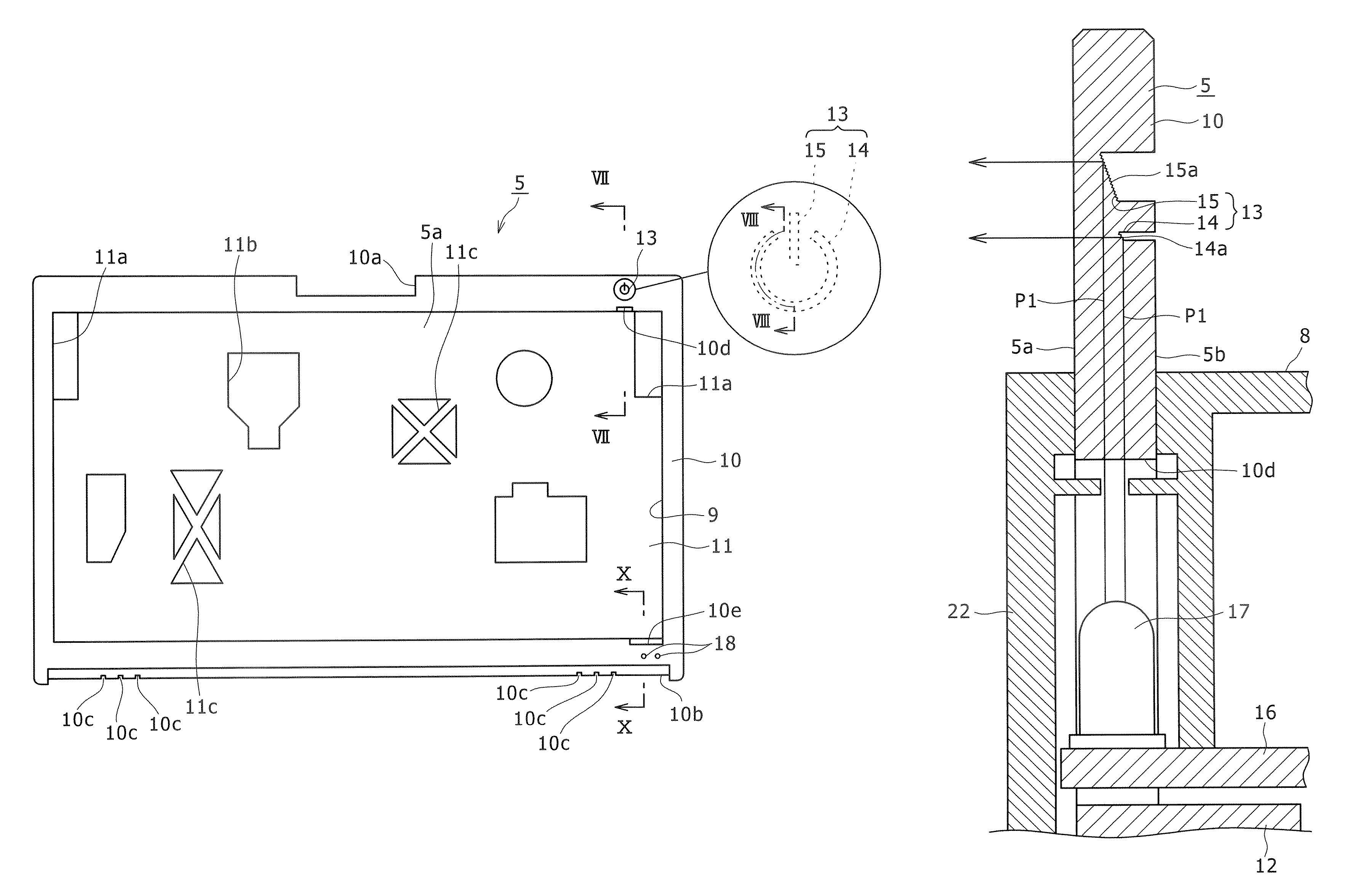
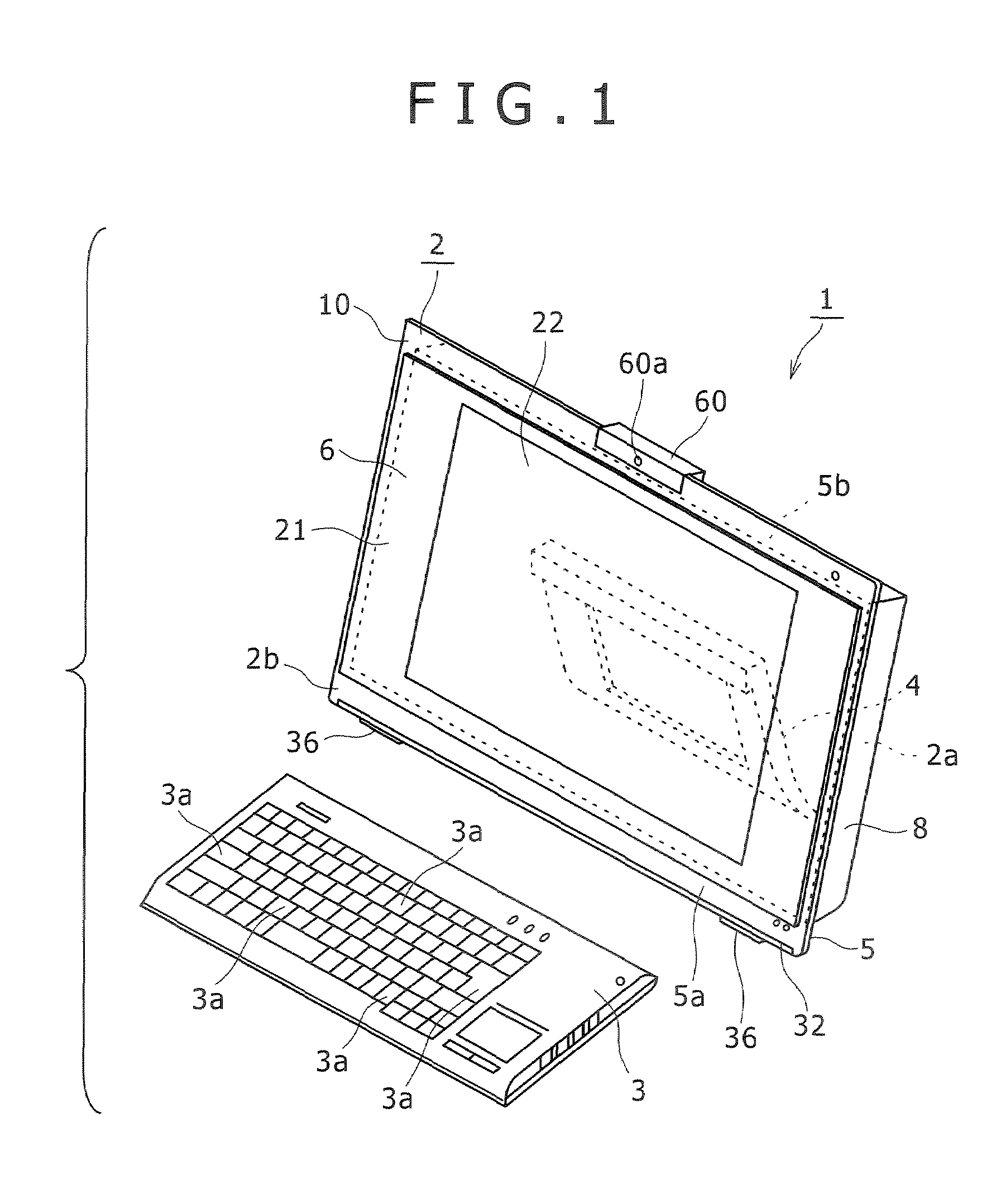
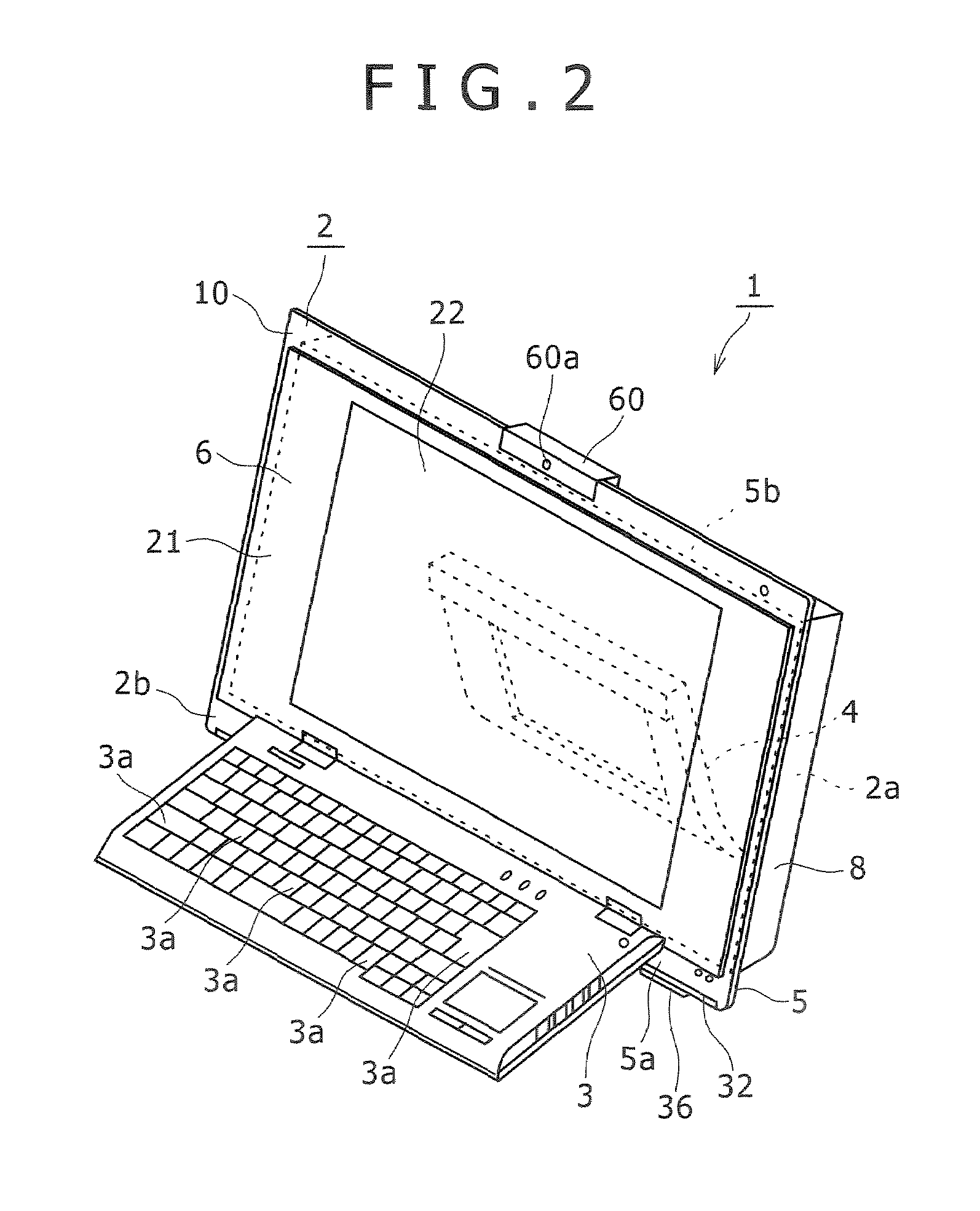
The present invention provides an electronic apparatus with a simplified structure and enhanced visual observability of a lamp section. The apparatus includes a base chassis formed as a unitary member from a transparent material and having two faces positioned on the opposite sides to each other. A display unit with a display panel attached to the first mounting face section of the base chassis, a control circuit board attached to the second mounting face section, a rear cover attached to the second mounting face section and configured to cover the control circuit board, a device mounting board having a semiconductor light emitting element disposed thereon, and a luminous lamp section or a reflecting lamp section formed at a position of the base chassis on the outer side of the display unit. The luminous lamp section or the reflecting lamp section receives and emits light emitted from the semiconductor light emitting element and passes through the inside of the base chassis. The apparatus provides enhancement of the visual observability while the simple structure of the lamp section is maintained.

Problems solved by technology

However, in the existing electronic apparatus described above, since the light passing member and the front glass plate are provided such that light emitted from the light emitting section passes through both of them, there is a problem that the structure is complicated.

Method used


Image

  • Electronic apparatus emitting light through a unitary transparent base chassis
  • Electronic apparatus emitting light through a unitary transparent base chassis
  • Electronic apparatus emitting light through a unitary transparent base chassis

Examples


Embodiment Construction

[0048]In the following, the present invention is described in connection with a preferred embodiment thereof. In the embodiment described, the present invention is applied to an electronic apparatus in the form of a personal computer.

[0049]It is to be noted that the application of the electronic apparatus according to the present invention is not limited to a personal computer, but the electronic apparatus of the present invention can be applied widely to various electronic apparatus such as information processing apparatus such as, for example, a personal digital assistant (PDA), a network terminal, a portable information terminal and a working station, acoustic apparatus, electronic appliances for home use and so forth.

[0050]In the following description, for the convenience of illustration and description, upward, downward, forward, rearward, leftward and rightward directions are defined with respect to the direction in which a user visually observes the display screen of the pers...


PUM


Abstract

Disclosed herein is an electronic apparatus, including: a base chassis formed as a unitary member from a transparent material and having two faces positioned on the opposite sides to each other and individually formed as first and second mounting face sections; a display unit having a display panel thereon and attached to said first mounting face section; a control circuit board attached to said second mounting face section; a rear cover attached to said second mounting face section and configured to cover said control circuit board; a device mounting board having a semiconductor light emitting element disposed thereon; and a luminous lamp section formed at a position of said base chassis on the outer side of said display unit and configured to receive and emit light having been emitted from said semiconductor light emitting element and passed through the inside of said base chassis.

Description

CROSS REFERENCES TO RELATED APPLICATIONS[0001]The present invention contains subject matter related to Japanese Patent Application JP 2006-108662 filed in the Japan Patent Office on Apr. 11, 2006, the entire contents of which being incorporated herein by reference.BACKGROUND OF THE INVENTION[0002]1. Field of the Invention[0003]This invention relates to an electronic apparatus, and more particularly to an electronic apparatus which includes a lamp section for indicating a predetermined operation state.[0004]2. Description of the Related Art[0005]An electronic apparatus such as, for example, a personal computer, a personal digital assistant (PDA), a television receiver or an acoustic apparatus includes a lamp section for indicating a predetermined operation state such as a power supply state or an operation state of a drive. In some electric apparatus, the lamp section is formed by working a transparent material. An electronic apparatus of the type described is disclosed, for example,...

Claims


Application Information

Patent Timeline
Patent Type & Authority Patents(United States)
IPC IPC(8): G01D11/28F21V7/04
CPCG06F1/1615G06F1/1616G06F1/1656G06F1/1686G06F1/1677G06F1/1679G06F1/166G06F2200/161H05K5/0204H05K5/0234
Inventor YUKAWA, SHUHEITANAKA, MASAFUMIOGASAWARA, YUTAKAKURONUMA, TOORU
Owner SONY CORP
Learn More