
Vehicle power unit with improved lubrication oil recovery structure

a technology of lubrication oil and recovery structure, which is applied in the direction of machines/engines, jet propulsion mounting, gearing, etc., can solve the problems of deterioration in power transmission efficiency, achieve easy discharge, reduce the amount of oil pump, and increase the difference in height

Active Publication Date: 2010-04-13
HONDA MOTOR CO LTD
View PDF12 Cites 14 Cited by
  • Summary
  • Abstract
  • Description
  • Claims
  • Application Information

AI Technical Summary

Benefits of technology

This configuration enhances lubricating oil return efficiency, reduces stirring resistance in the gear train, and minimizes the risk of air lock in the oil pump, while facilitating maintenance and gear ratio adjustments by exposing key components for easy access.

Problems solved by technology

Therefore, gearwheels carried on a shaft whose height from the oil storage portion is small are met with great stirring resistance, which may possibly lead to deterioration in power transmission efficiency.

Method used


Image

  • Vehicle power unit with improved lubrication oil recovery structure
  • Vehicle power unit with improved lubrication oil recovery structure
  • Vehicle power unit with improved lubrication oil recovery structure

Examples


Embodiment Construction

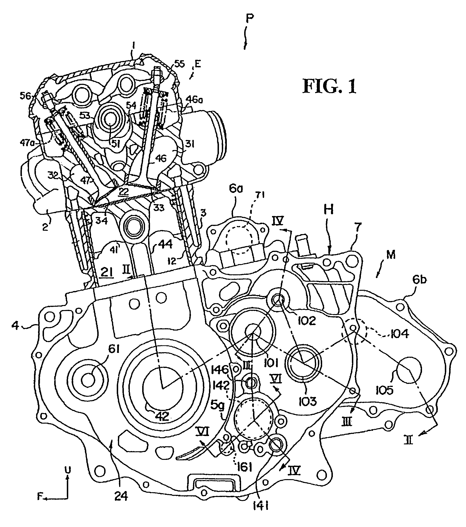
[0032]Selected illustrative embodiments of the invention will now be described in some detail, with reference to the drawings. It should be understood that only structures considered necessary for clarifying the present invention are described herein. Other conventional structures, and those of ancillary and auxiliary components of the system, are assumed to be known and understood by those skilled in the art. In the figures, arrows U and F denote the upper side and front, respectively, and references to left and right directions are made with respect to the front.

[0033]FIG. 1 is a cross-sectional view of a power unit P of a saddle-ride type vehicle as viewed from the left side, the power unit being provided with a lubricating device according to the present invention. Saddle-type vehicles are characterized by a seat which is straddled by the vehicle operator. Examples of saddle-ride type vehicles include, but are not limited to, four-wheeled all-terrain vehicles, motorcycles, and j...


PUM


Abstract

A power unit of a vehicle, which includes an internal combustion engine and a transmission, is provided which is configured to quickly return lubricating oil fed to the transmission to an oil storage portion of the power unit case. The transmission includes a gear train housed in a gear chamber, the gear train executing power transmission among an input shaft, an intermediate shaft and an output shaft. The input shaft and the output shaft are arranged such that a line connecting their respective shaft centers extends almost horizontally above a communicating port which permits return oil flow between segregated portions of the power unit case. In addition, the intermediate shaft is disposed above and between the input shaft and the output shaft.

Description

CROSS-REFERENCE TO RELATED APPLICATIONS[0001]The present invention claims priority under 35 USC 119 based on Japanese patent application No. 2006-146731, filed on May 26, 2006. The subject matter of this priority document is incorporated by reference herein.BACKGROUND OF THE INVENTION[0002]1. Field of the Invention[0003]The present invention relates to a vehicle power unit, the power unit including an internal combustion engine and a transmission, the transmission modifying the rotational speed of the engine and transmitting the rotational driving force of the engine to vehicle wheels.[0004]2. Description of the Background Art[0005]In a known a vehicle power unit, which includes an internal combustion engine and a transmission, the transmission is configured to include input and output shafts disposed parallel to each other, and to further include a plurality of gear trains arranged between the input and output shafts. Such a power unit is disclosed, for example, in Japanese Patent ...

Claims


Application Information

Patent Timeline
Patent Type & Authority Patents(United States)
IPC IPC(8): B60K17/08F16H57/02F16H57/04
CPCF16H57/04F01M11/02F02B61/02F16H57/02Y10T74/19219F16H2057/02065Y10T74/2186Y10T74/2185Y10T74/2189F16H2057/0203
Inventor NISHI, TORUMOHARA, TOSHINARI
Owner HONDA MOTOR CO LTD
Learn More