
In-plane switching mode liquid crystal display device having a biaxial optically anisotropic member

a liquid crystal display and biaxial optical anisotropy technology, applied in non-linear optics, instruments, optics, etc., can solve the problems of reducing the angle of field, difficulty in watching images, and large variation in brightness, color and contrast, etc., to achieve excellent antireflection properties, excellent contrast, and uniform display of images

Active Publication Date: 2010-04-06
ZEON CORP
View PDF23 Cites 3 Cited by
  • Summary
  • Abstract
  • Description
  • Claims
  • Application Information

AI Technical Summary

Benefits of technology

The present invention provides a liquid crystal display device with excellent antireflection properties, scratch resistance, durability, and a wide angle of field. The device includes an optically anisotropic member with a negative value of intrinsic birefringence and a polarizer at each side of the liquid crystal cell. The refractive index of the optically anisotropic member in the direction of the in-plane slow axis is represented by nz, and the refractive index in the direction of the absorption axis of the polarizer is represented by nx and ny. The in-plane slow axis of the optically anisotropic member and the absorption axis of the polarizer are disposed at relative positions approximately parallel or approximately perpendicular to each other. The device also includes a protective film on at least one face of the polarizer. The invention provides a flat panel display with a great area and uniform display of images at any angle of observation.

Problems solved by technology

It has been pointed out that liquid crystal display devices have a drawback in that brightness, color and contrast vary to a great extent and difficulty arises in watching images when the images are observed at oblique angles.
However, in accordance with this technology, the arrangement of polarizer plates shifts from the cross-nichol arrangement depending on the angle of observation, and this causes a decrease in the angle of field due to leak of light although the decrease in the angle of field due to the liquid crystal molecules in the liquid crystal cell is relatively suppressed.
However, none of these means are sufficient for providing a liquid crystal display device which exhibits uniform display of images with a great contrast at any angle of observation, and further improvement has been desired.

Method used


Image

  • In-plane switching mode liquid crystal display device having a biaxial optically anisotropic member
  • In-plane switching mode liquid crystal display device having a biaxial optically anisotropic member
  • In-plane switching mode liquid crystal display device having a biaxial optically anisotropic member

Examples


first embodiment

(I-1) the Preferable Arrangement

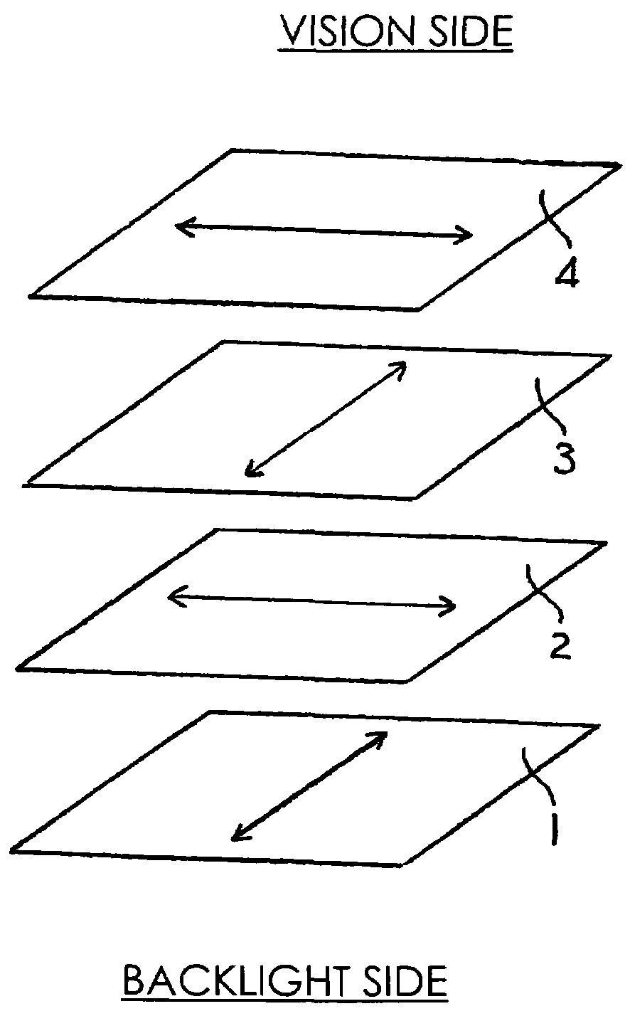
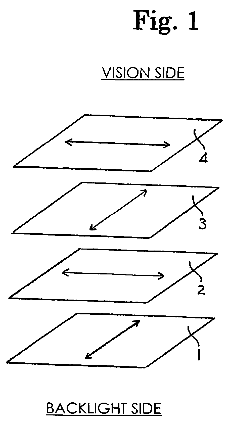
[0100]FIG. 3 shows a diagram exhibiting the first embodiment of the preferable arrangement (referred to as arrangement I-1, hereinafter) of the liquid crystal display device of the present invention. In arrangement I-1, it is preferable that the absorption axis of the polarizer at the output side and the in-plane slow axis of the liquid crystal of the liquid crystal cell under application of no voltage are disposed at relative positions parallel to each other, and the slow axis of optically anisotropic member and the in-plane slow axis of the liquid crystal of the liquid crystal cell under application of no voltage are disposed at relative positions perpendicular to each other. Due to the above relative positions of the optically anisotropic member, the liquid crystal cell and the two polarizers, the minimum value of the contrast can be made 30 or greater at polar angles of 0 to 80°.

second embodiment

(I-2) the Preferable Arrangement

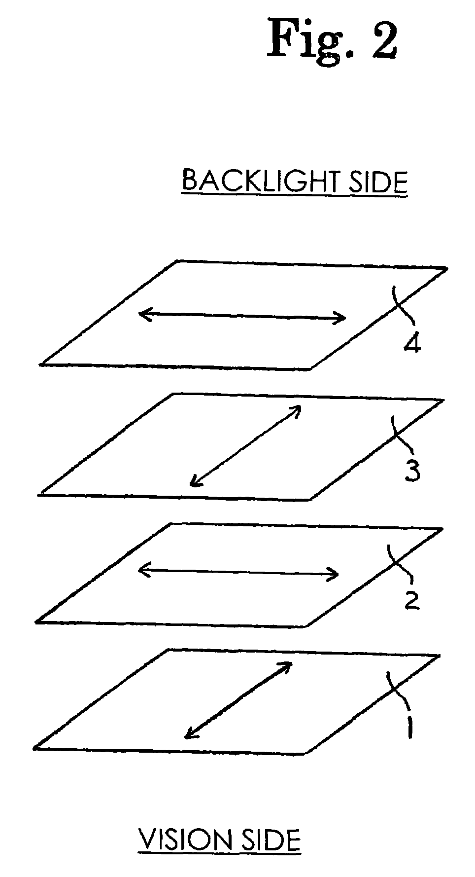
[0101]FIG. 4 shows a diagram exhibiting the second embodiment of the preferable arrangement (referred to as arrangement I-2, hereinafter) of the liquid crystal display device of the present invention. In arrangement I-2, it is preferable that the absorption axis of the polarizer at the output side and the in-plane slow axis of the liquid crystal of the liquid crystal cell under application of no voltage are disposed at relative positions parallel to each other, and the slow axis of optically anisotropic member and the in-plane slow axis of the liquid crystal of the liquid crystal cell under application of no voltage are disposed at relative positions parallel to each other. Due to the above relative positions of the optically anisotropic member, the liquid crystal cell and the two polarizers, the minimum value of the contrast can be made 30 or greater at polar angles of 0 to 80°.

[0102]In arrangements I-1 and I-2 the preferable combination of the in-pl...

preparation example 1

Preparation of a Film of an Optically Anisotropic Member

[0120]A long sheet of an unstretched laminate which comprised layer [1] comprising a norbornene-based polymer [manufacture by NIPPON ZEON Co., Ltd.; ZEONOR 1020; the glass transition temperature: 105° C.], layer [2] comprising a styrene-maleic anhydride copolymer [manufactured by NOVA CHEMICAL JAPAN Co., Ltd.; DYLARK D332; the glass transition temperature: 130° C.; the content of oligomer components: 3% by weight] and layer [3] comprising a modified ethylene-vinyl acetate copolymer [manufactured by MITSUBISHI KAGAKU Co., Ltd.; MODIC AP A543, the Vicat softening point: 80° C.] and had a structure of layer [1] (15 μm)—layer [3] (5 μm)—layer [2] (110 μm)—layer [3] (5 μm)—layer [1] (15 μm) was obtained in accordance with the coextrusion molding. The long sheet of an unstretched laminate was uniaxially stretched by a tenter in the longitudinal direction at a temperature of 136° C. to a stretching ratio of 1.3 and then in the transve...


PUM

PropertyMeasurementUnit
thicknessaaaaaaaaaa
thicknessaaaaaaaaaa
transparentaaaaaaaaaa

Abstract

A liquid crystal display device of an in-plane switching mode comprises at least an optically anisotropic member and a liquid crystal cell disposed between a pair of polarizers having absorption axes disposed approximately perpendicularly to each other, wherein nz>nx>ny (nx: a refractive index (n) in the direction of the in-plane slow axis; ny: n in the in-plane direction perpendicular to the above direction; nz: n in the direction of thickness, each at 550 nm); the optically anisotropic member comprises a layer comprising a material having a negative value of intrinsic birefringence; and the in-plane slow axis of the optically anisotropic member is approximately parallel or perpendicular to the absorption axis of a polarizer closer to the member. The antireflection property, scratch resistance and durability are excellent, the angle of field is wide, and uniform display of images with great contrast can be achieved at any angle of observation.

Description

TECHNICAL FIELD[0001]The present invention relates to a liquid crystal display device. More particularly, the present invention relates to a liquid crystal display device which exhibits excellent antireflection property, scratch resistance and durability, provides a wide angle of field and achieves uniform display of images with great contrast at any angle of observation.BACKGROUND ART[0002]Liquid crystal display devices are characterized by the high quality of images, the small thickness, the light weight and the small consumption of electric power and widely used for televisions, personal computers and automobile navigators. It has been pointed out that liquid crystal display devices have a drawback in that brightness, color and contrast vary to a great extent and difficulty arises in watching images when the images are observed at oblique angles.[0003]To overcome the drawback, improvements in the design of the liquid crystal cell itself have been studied, and a liquid crystal dis...

Claims


Application Information

Patent Timeline
Patent Type & Authority Patents(United States)
IPC IPC(8): G02F1/1335G02F1/1343
CPCG02F1/133634G02F1/134363G02F2413/12G02F2413/01G02F1/1335G02F1/13363
Inventor ITADANI, MOTOHIROOKUDE, SHUHEIYAMANAKA, SHUNSUKEARAKAWA, KOHEI
Owner ZEON CORP
Learn More