Liquid crystal display device
a liquid crystal display and display device technology, applied in liquid crystal compositions, instruments, chemistry apparatus and processes, etc., can solve the problems of reducing the angle of field, difficulty in watching images, and large variation in brightness, color and contrast, etc., to achieve excellent antireflection properties, excellent contrast, and uniform display of images
- Summary
- Abstract
- Description
- Claims
- Application Information
AI Technical Summary
Benefits of technology
Problems solved by technology
Method used
Image

Examples
first embodiment
(1-I) the Preferable Arrangement
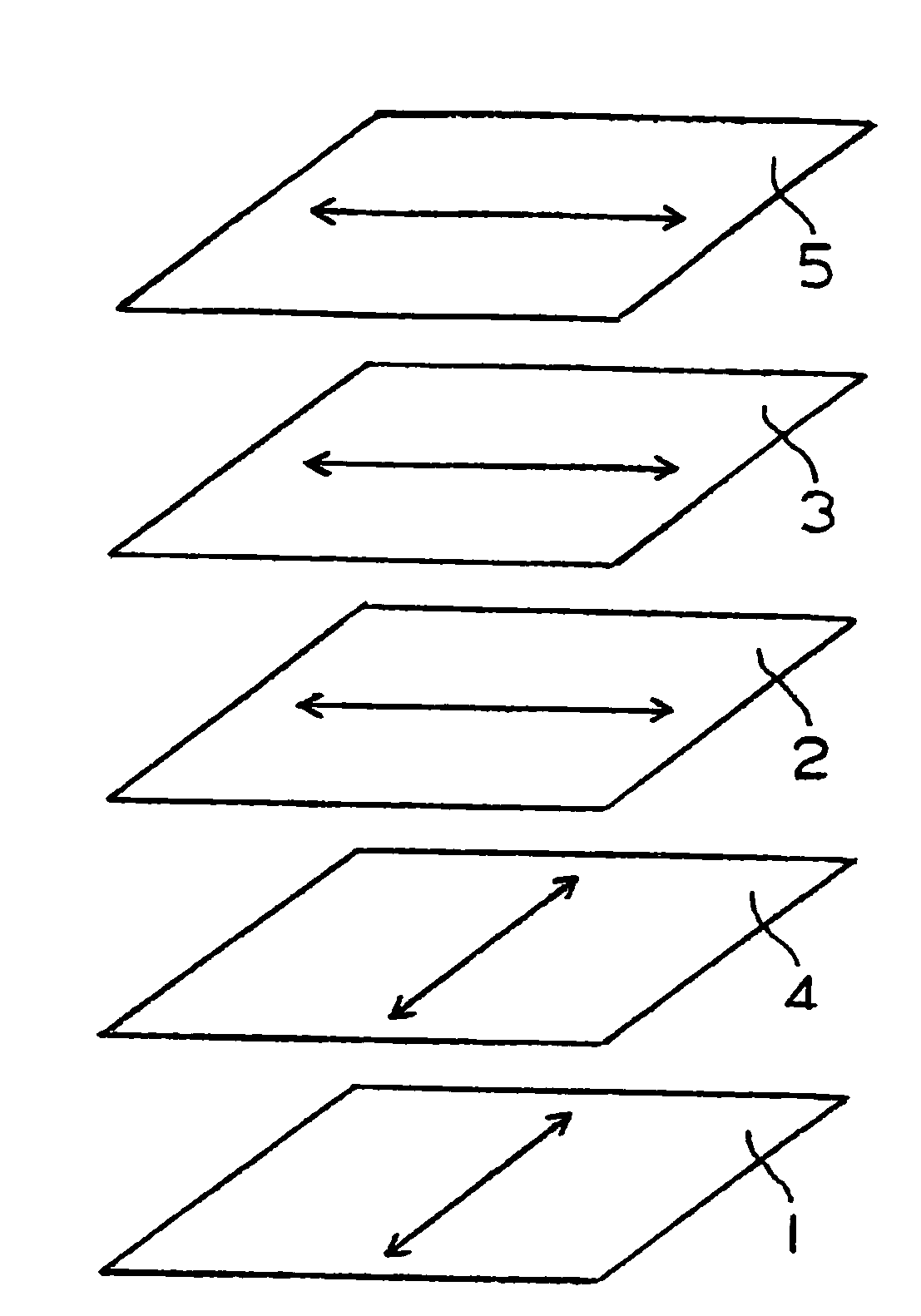
[0154]FIG. 3 shows a diagram exhibiting the first embodiment of the preferable arrangement (referred to as arrangement 1-I, hereinafter) of the liquid crystal display device of the present invention. In arrangement 1-I, the absorption axis of the polarizer at the output side and the in-plane slow axis of the liquid crystal of the liquid crystal cell under application of no voltage are disposed at relative positions parallel to each other. Optically anisotropic member (A) and optically anisotropic member (B) are disposed between the liquid crystal cell and the polarizer at the incident side. The in-plane slow axes of optically anisotropic member (A) and optically anisotropic member (B) are disposed at relative positions approximately perpendicular to each other. It is preferable that the in-plane slow axis of optically anisotropic member (B) and the in-plane slow axis of the liquid crystal cell under application of no voltage are disposed at relative p...
second embodiment
(1-II) the Preferable Arrangement
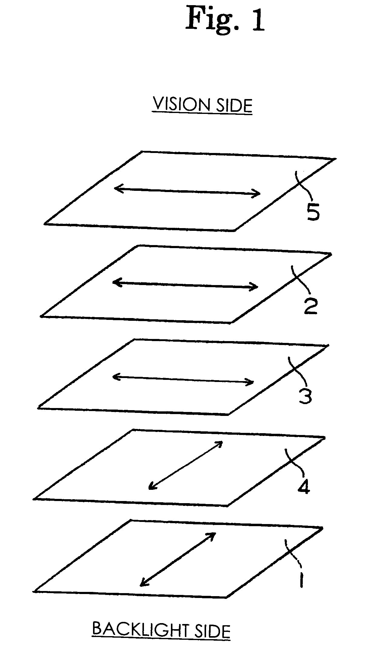
[0158]FIG. 4 shows a diagram describing the second embodiment of the preferable arrangement (referred to as arrangement 1-II, hereinafter) of the liquid crystal display device of the present invention. In arrangement 1-II, the absorption axis of the polarizer at the output side and the in-plane slow axis of the liquid crystal cell of the liquid crystal cell under application of no voltage are disposed at relative positions parallel to each other. Optically anisotropic member (A) and optically anisotropic member (B) are disposed between the liquid crystal cell and the polarizer at the output side. The in-plane slow axes of optically anisotropic member (A) and optically anisotropic member (B) are disposed at relative positions approximately perpendicular to each other. It is preferable that the in-plane slow axis of optically anisotropic member (B) and the in-plane slow axis of the liquid crystal cell under application of no voltage are disposed at rel...
third embodiment
(1-III) the Preferable Arrangement
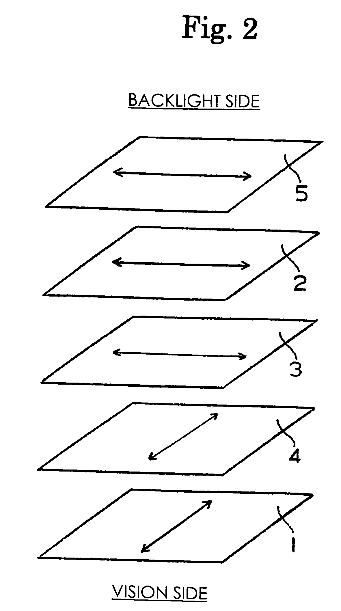
[0161]FIG. 5 shows a diagram describing the third embodiment of the preferable arrangement (referred to as arrangement 1-III, hereinafter) of the liquid crystal display device of the present invention. In arrangement 1-III, the absorption axis of the polarizer at the output side and the in-plane slow axis of the liquid crystal of the liquid crystal cell under application of no voltage are disposed at relative positions parallel to each other. Optically anisotropic member (A) and optically anisotropic member (B) are separately disposed between the liquid crystal cell and the polarizer at the incident side and between the liquid crystal cell and the polarizer at the output side. It is preferable that the in-plane slow axis of optically anisotropic member (B) and the in-plane slow axis of the liquid crystal cell under application of no voltage are disposed at relative positions approximately perpendicular to each other, and optically anisotropic member...
PUM
| Property | Measurement | Unit |
|---|---|---|
| thickness | aaaaa | aaaaa |
| average oblique angle | aaaaa | aaaaa |
| oblique angle | aaaaa | aaaaa |
Abstract
Description
Claims
Application Information
 - R&D
- Intellectual Property
- Life Sciences
- Materials
- Tech Scout
- Unparalleled Data Quality
- Higher Quality Content
- 60% Fewer Hallucinations
Browse by: Latest US Patents, China's latest patents, Technical Efficacy Thesaurus, Application Domain, Technology Topic, Popular Technical Reports.
© 2025 PatSnap. All rights reserved.Legal|Privacy policy|Modern Slavery Act Transparency Statement|Sitemap|About US| Contact US: help@patsnap.com