Apparatus for generating power responsive to mechanical vibration

a technology of mechanical vibration and apparatus, applied in the field of miniature sensors, can solve the problems of chemical power supplies that are not suitable for the application, the amount of light or thermal energy, and the inability to consider nor suggest any solution to fabricate electromagnetic micro-generators

Inactive Publication Date: 2010-04-06
THE UNITED STATES OF AMERICA AS REPRESENTED BY THE SECRETARY OF THE NAVY
View PDF8 Cites 14 Cited by
  • Summary
  • Abstract
  • Description
  • Claims
  • Application Information

AI Technical Summary

Problems solved by technology

Chemical power supply (battery) technology is well-developed for such applications but, where shelf life or replacement accessibility is a limiting factor, chemical power supplies may not be suitable for the application.
However, there are many applications where there is an insufficient amount of light or thermal energy such as in medical implants.
Ghezzo et al. employ varying capacitance and neither consider nor suggest any solution the problem of fabricating an electromagnetic micro-generator.
These devices are thereby limited in power output capacity by the limited mass of the single magnet, the limited room for a number of coils in the flux field of the single magnet and the limited flux slope available at the coils because of the single magnetic pole exposed thereto.

Method used


Image

  • Apparatus for generating power responsive to mechanical vibration
  • Apparatus for generating power responsive to mechanical vibration
  • Apparatus for generating power responsive to mechanical vibration

Examples


Embodiment Construction

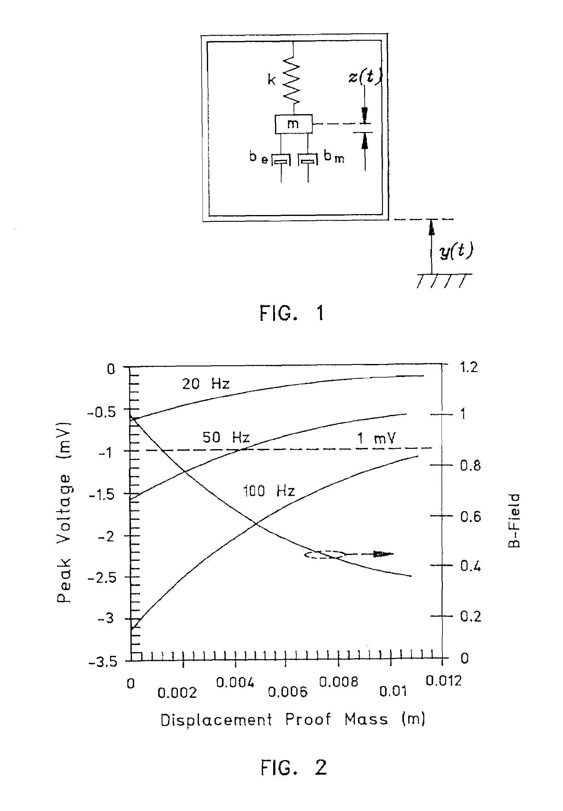
[0032]FIG. 1 is a schematic diagram illustrating a damped mass-spring model representative of the micro-generator system of this invention. Both electrical and mechanical damping must be considered in analyzing and optimizing the design for particular ambient vibration spectra. Referring to FIG. 1, for time t, a mass m, a spring constant k, an electrical damping factor be, a mechanical damping factor bm, and a displacement function z(t), the power P available from the coil current may be expressed as shown in Eqn. 1:

[0033]P=∫0v⁢F⁢⁢ⅆv=∫0v⁢be⁢z.⁢⁢ⅆv=be⁢∫0v⁢v⁢⁢ⅆv=12⁢be⁢v2=12⁢be⁢z.2[Eqn.⁢1]

Conservation of energy leads to Eqn. 2:

m{umlaut over (z)}+(be+bm)ż+kz=−mÿ  [Eqn. 2]

Laplacian transformation and the substitution of variables can be shown to provide the following Eqns. 3-10:

[0034]Z=-ms2⁢Yms2+(be+bm)⁢s+k[Eqn.⁢3]Let⁢:⁢⁢be=2⁢⁢m⁢⁢ξe⁢ωn⁢⁢bm=2⁢⁢m⁢⁢ξm⁢ωn[Eqns.⁢4]

where ωn2=k / m.

[0035]Thus,⁢Z.=-jω⁡(ωωn2)2⁢(ξe+ξn)⁢jωωn+1-(ωωn)2⁢Y[Eqn.⁢5]and⁢⁢P=m⁢⁢ξe⁢ωn⁢ω2⁡(ωωn)3⁢Y2[(2⁢(ξe+ξm)⁢ωωn)+(1-(ωωn)2)]2[...


PUM


Abstract

A vibrational energy harvesting apparatus comprising: a substrate having a plurality of integral compliant regions; at least two ferromagnetic masses each coupled to a corresponding one or more of the integral compliant regions such that at least one of the ferromagnetic masses moves with respect to the substrate responsive to substrate acceleration, each ferromagnetic mass having an inner magnetic pole disposed such that the inner magnetic poles are separated by a gap, wherein the magnetic polarities of the inner magnetic poles on the opposing sides of the gap are similar; wherein the inner magnetic poles form a steep flux gradient region in and around the gap; and a coil coupled to the substrate and disposed within the steep flux gradient region where it is exposed to a changing magnetic flux arising from motion of at least one of the ferromagnetic masses with respect to the substrate.

Description

CROSS-REFERENCE TO RELATED APPLICATION[0001]This application is a continuation application of U.S. patent application Ser. No. 10 / 911,748 (NC #84774), filed 27 Jul. 2004 now U.S. Pat. No. 7,501,726, titled “Micro-Electro-Mechanical System (MEMS) and Apparatus for Generating Power Responsive to Mechanical Vibration,”, which is incorporated herein by this reference.STATEMENT OF GOVERNMENT INTEREST[0002]The invention described herein may be manufactured and used by or for the Government of the United States of America for Governmental purpose without the payment of any royalties thereon or therefore.FEDERALLY-SPONSORED RESEARCH AND DEVELOPMENT[0003]This application is assigned to the United States Government and is available for licensing for commercial purposes. No license is necessary when used for Governmental purposes. Licensing and technical inquiries should be directed to the Office of Patent Counsel, Space and Naval Warfare Systems Center, San Diego, Code 20012, San Diego, Calif...

Claims


Application Information

Patent Timeline
Patent Type & Authority Patents(United States)
IPC IPC(8): H02K33/00
CPCH02K35/00Y10T29/49009
Inventor WATERS, RICHARD L.SULLIVAN, PATRICK M.HUNT, BARRY R.
Owner THE UNITED STATES OF AMERICA AS REPRESENTED BY THE SECRETARY OF THE NAVY
Why Eureka
Try Eureka