
Deep fat tube fryer burner assembly

a technology of burner assembly and deep fat tube, which is applied in the direction of gaseous heating fuel, combustion types, stoves or ranges, etc., can solve the problems of inconvenient use, inconvenient maintenance and repair, and the rigid mounting of burners, so as to achieve maximum burner efficiency and control by the user, and prevent substantial movement of burners. , the effect of increasing the burner efficiency

Inactive Publication Date: 2010-04-06
THE FRYMASTER CORP LLC
View PDF6 Cites 11 Cited by
  • Summary
  • Abstract
  • Description
  • Claims
  • Application Information

AI Technical Summary

Benefits of technology

The solution provides increased burning efficiency, improved heat transfer, and simplified maintenance by ensuring efficient air-fuel mixing and reducing service time through a secure, easy-to-assemble burner configuration.

Problems solved by technology

One other difficulty with conventional deep fat tube fryers is that the burners are rigidly mounted to the heat exchanger tubes, or mounted to the heat exchanger tubes with a number of fasteners.
Either of these configurations requires a significant amount of time for service and repair.
The co-axial orientation often requires that the burner be shorter than what optimal burning conditions would require, due to space limitations.
Those burners that use an angled mounting orientation are not desirable because they force the combustion gas down into the heat exchanger tube, against the forces of gravity and / or buoyancy.
This is not an ideal condition to facilitate the mixing of the gas fuel with air.
These configurations are undesirable because they decrease the efficiency with which the combustion gasses are mixed and burned.

Method used


Image

  • Deep fat tube fryer burner assembly
  • Deep fat tube fryer burner assembly
  • Deep fat tube fryer burner assembly

Examples


Embodiment Construction

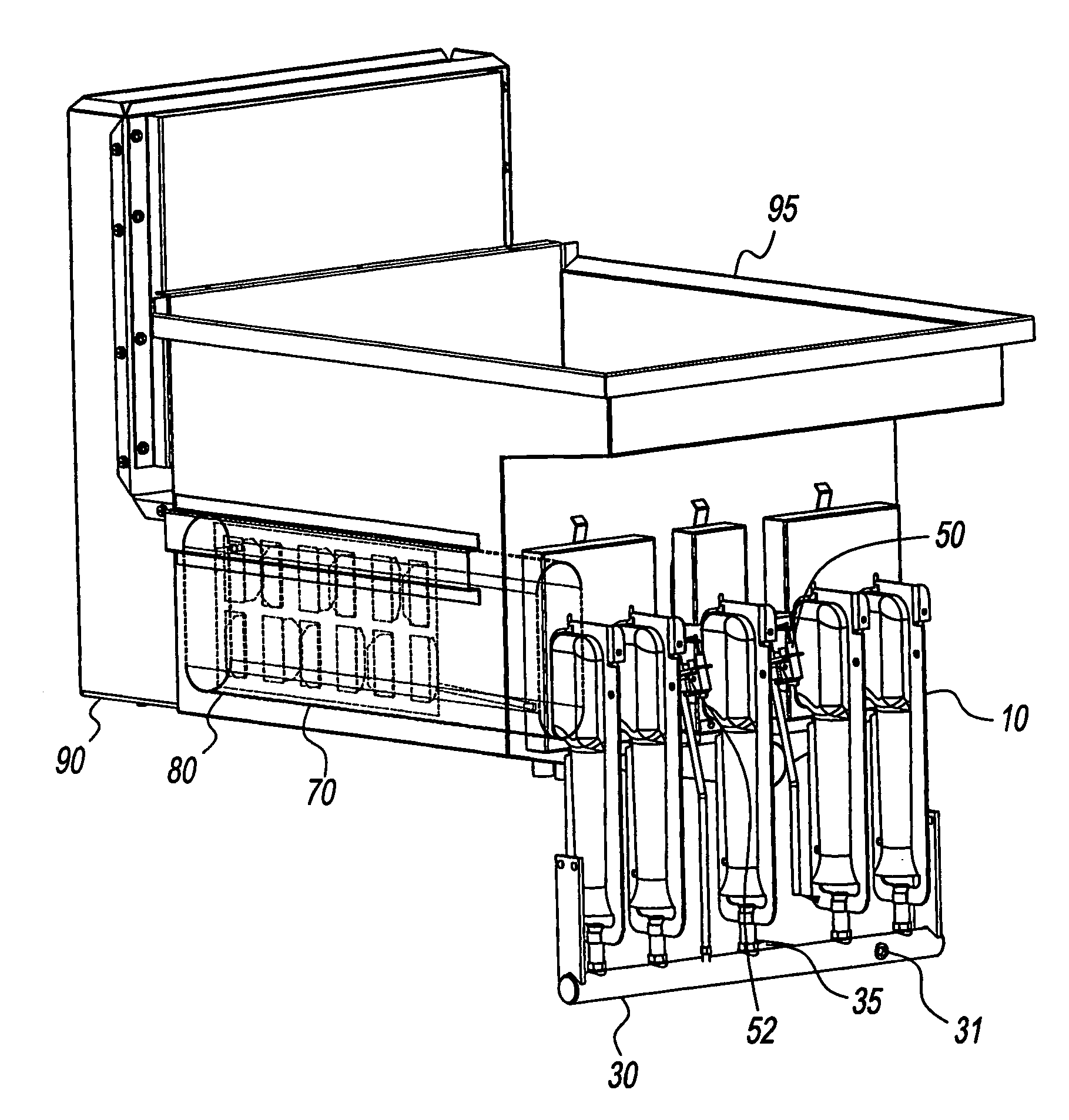
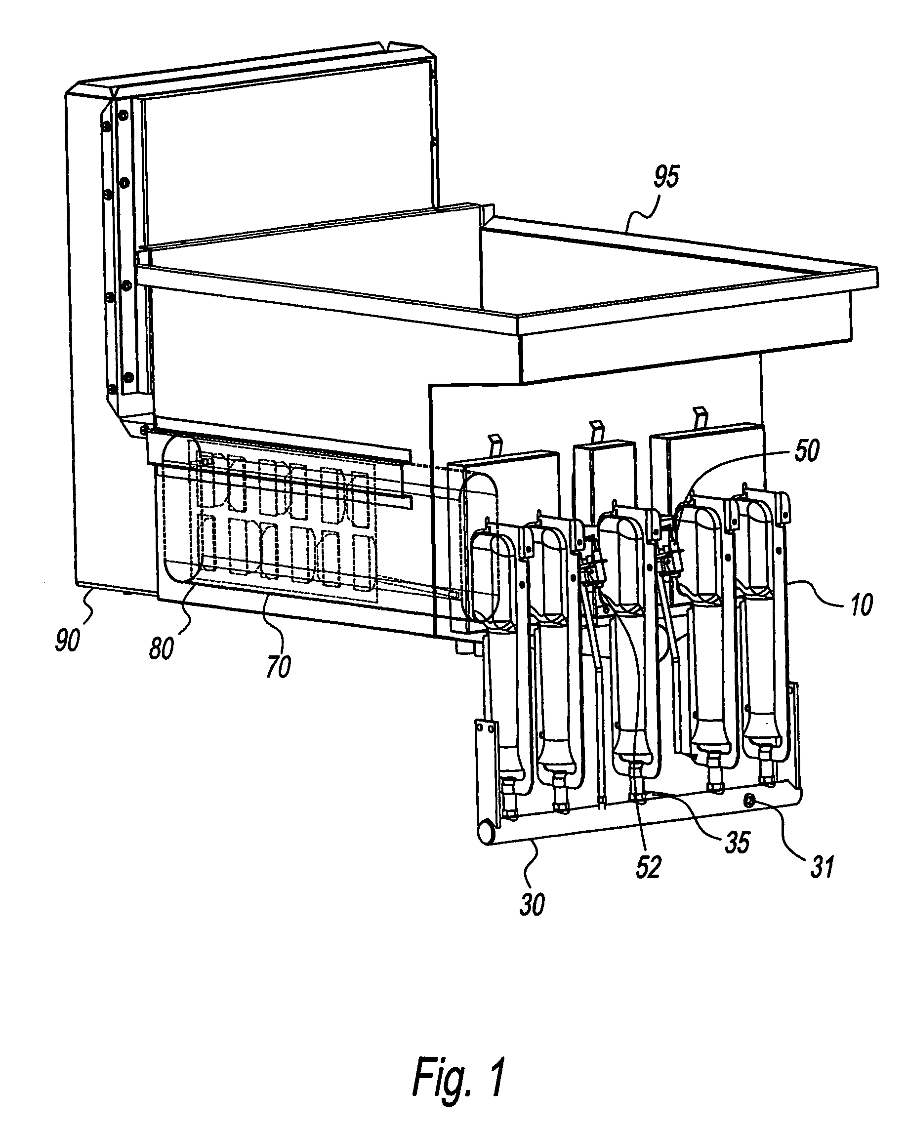
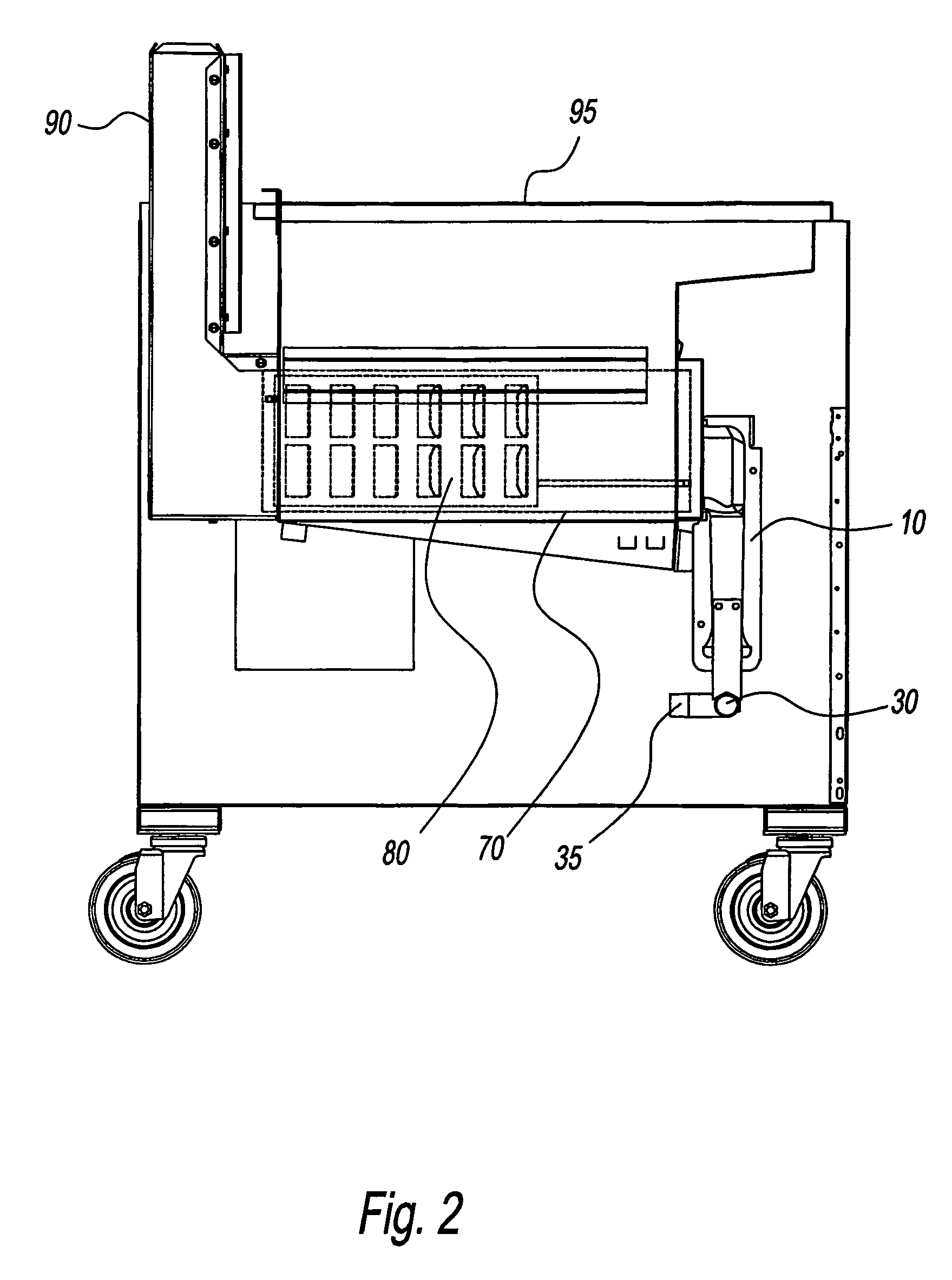
[0030]Referring to FIGS. 1 and 2, an assembly of five burners 10, gas manifold 30, heat exchanger tube 70, heat transfer baffle 80, flue 90, and frypot 95 are shown. Gas manifold 30 can have manifold testing port 31, which during maintenance can be used to ensure that a proper amount of gas is flowing through the manifold at an adequate pressure. Manifold testing port 31 remains sealed during fryer operation. Gas manifold 30 also has gas inlet 35. When the burner assembly is in use, combustion gas is introduced into gas manifold 30 through gas inlet 35 and travels up through burners 10, as is discussed in further detail below.

[0031]Referring to FIGS. 3, 4, and 5, an enlarged view of burner 10 is shown. The body of burner 10 is formed from one continuous sheet of metal, which in the present embodiment is aluminized steel. The present invention, however, contemplates the use of other materials to form burner 10, such as galvanized or stainless steel. Burner 10 has right burner side 12...


PUM


Abstract

The gas tube fryer comprises substantially 90° in-shot burners, burner mounting boxes, a one-piece burner mounting bracket, and a bracket housing, all of which are used in conjunction with heat exchanger tubes, heat transfer baffles, a frypot, and a flue in a fryer. The burner mounting boxes are keyed specifically to the face of the burner, preventing substantial movement of the burners and introduction of ambient air into the heat exchange tubes. Each burner is also keyed to the mounting bracket, also preventing substantial movement and providing easy installation and repair. The ninety-degree orientation of the burners facilitates mixing of the combustion gases, and the burner comprises a screen on its face that helps to ensure maximum burner efficiency.

Description

CROSS-REFERENCE TO RELATED APPLICATION[0001]This application claims priority to U.S. Provisional Application Ser. No. 60 / 729,039, filed on Oct. 21, 2005.BACKGROUND OF THE INVENTION[0002]1. Field of the Invention[0003]The present disclosure relates to gas fryers. More particularly, the present disclosure relates to a gas fryer that utilizes burners and heat exchanger tubes to transfer heat to a cooking medium in a frypot.[0004]2. Description of the Related Art[0005]Deep fat tube fryers are well known in the field. These fryers typically include a frypot containing a cooking oil medium and one or more heat exchanger tubes that run through the frypot below the surface of the cooking oil. Burners are typically connected to one end of these heat exchanger tubes and heat the tube so that the heat is transferred to the cooking oil. A flue is usually used on the opposite end of the heat exchanger tube from the burner to discharge the combustion by-products. Often baffles are used inside the...

Claims


Application Information

Patent Timeline
Patent Type & Authority Patents(United States)
IPC IPC(8): F23C3/00
CPCA47J37/1247F23C3/002F23C3/004F23D14/045F23D14/70F23M9/06F24C3/085Y02B40/166F23D2900/00017F23D2900/14641F23D2213/00F23C5/02Y02B40/00
Inventor RICORD, CHARLES DAVIDHUTCHINSON, CHARLES MILTON
Owner THE FRYMASTER CORP LLC
Learn More