
Fleece-laying apparatus

a technology of laying apparatus and laying belt, which is applied in the direction of lap winding device, fibre treatment, textiles and paper, etc., can solve the problems of affecting the working speed of the belt, the overall effect of obtaining a very complicated routing of the two web conveyor belts, and the length of the belt is considerable, so as to achieve a simple and fast belt routing

Inactive Publication Date: 2010-04-06
DILO MASCHF OSKAR
View PDF7 Cites 10 Cited by
  • Summary
  • Abstract
  • Description
  • Claims
  • Application Information

AI Technical Summary

Benefits of technology

The present invention provides a fleece layer for a card web transport system that has a simplified routing of the belts involved in the transport and guidance of the card web, while also allowing for a high working speed. The invention uses a combination of a carriage cross-lapper and a sandwich layer, with an endless conveyor belt that travels around in the laying carriage and guides the card web in the laying gap. The conveyor belts have a smooth surface structure to ensure the smooth transport of the card web, while the laying carriage conveyor belt can have a smooth surface to cover the fleece on the output conveyor belt. The invention also offers the advantage of easy adjustment of the height of the web-guiding belts to accommodate different card web thicknesses.

Problems solved by technology

The two web conveyor belts cannot be routed so that they are parallel to each other at the lower deflecting roll in the upper carriage because different wrap-around radii are present, which would lead to frictional effects potentially damaging to the guided card web.
What is obtained overall, therefore, is a very complicated routing of the two web conveyor belts both in the upper carriage and in the laying carriage and also in the two tension carriages.
There are thus a large number of belt deflection points, and the belts are of considerable length.
As a result, the card web is exposed to strong aerodynamic influences, which are caused by the movement of the carriages and which can have the effect of blowing the fibers away and of causing the web to be deposited nonuniformly, especially at the edges of the laid nonwoven.
The working speed of a fleece layer of this type is therefore very limited.
Another disadvantage of the carriage cross-lappers mentioned above is that they cannot exert any pressure on the top side of the laid fleece without causing significant distortions, pile-ups, and folds in the fleece.

Method used


Image

  • Fleece-laying apparatus
  • Fleece-laying apparatus

Examples


Embodiment Construction

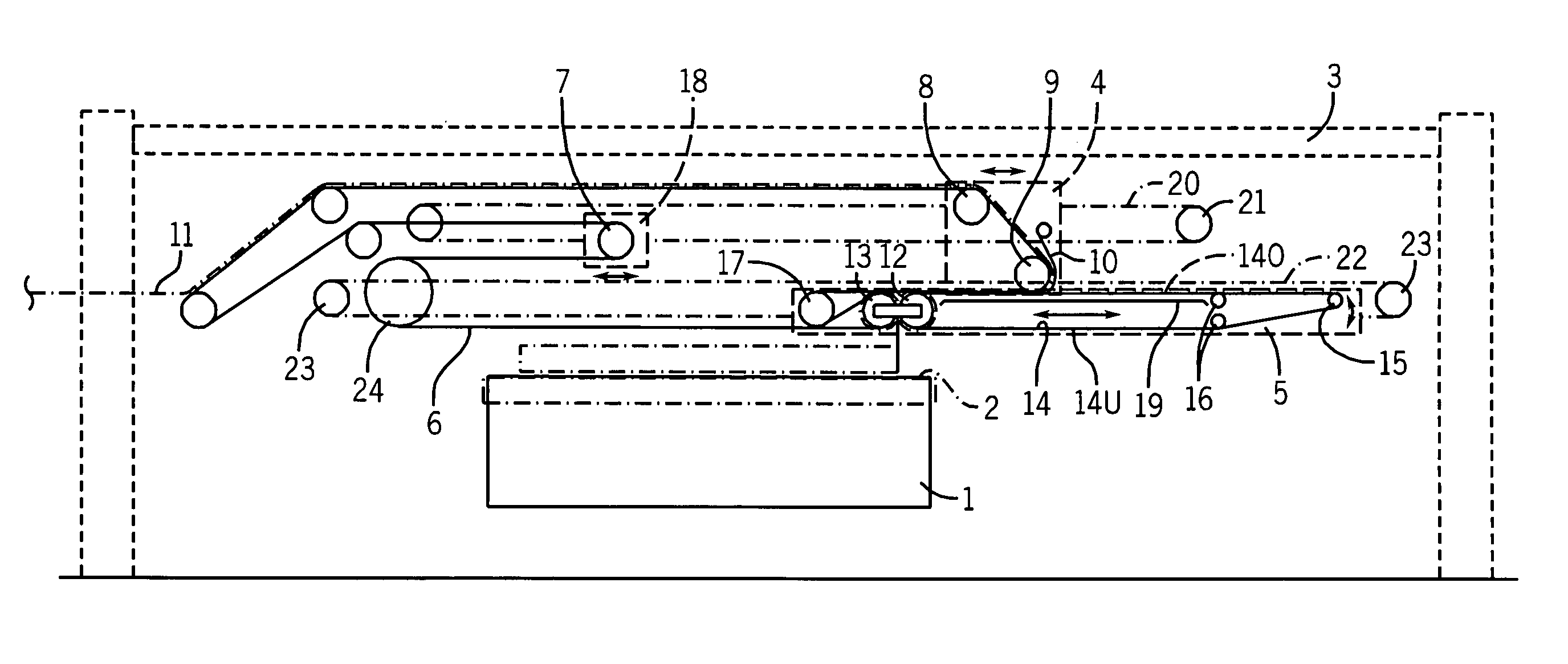
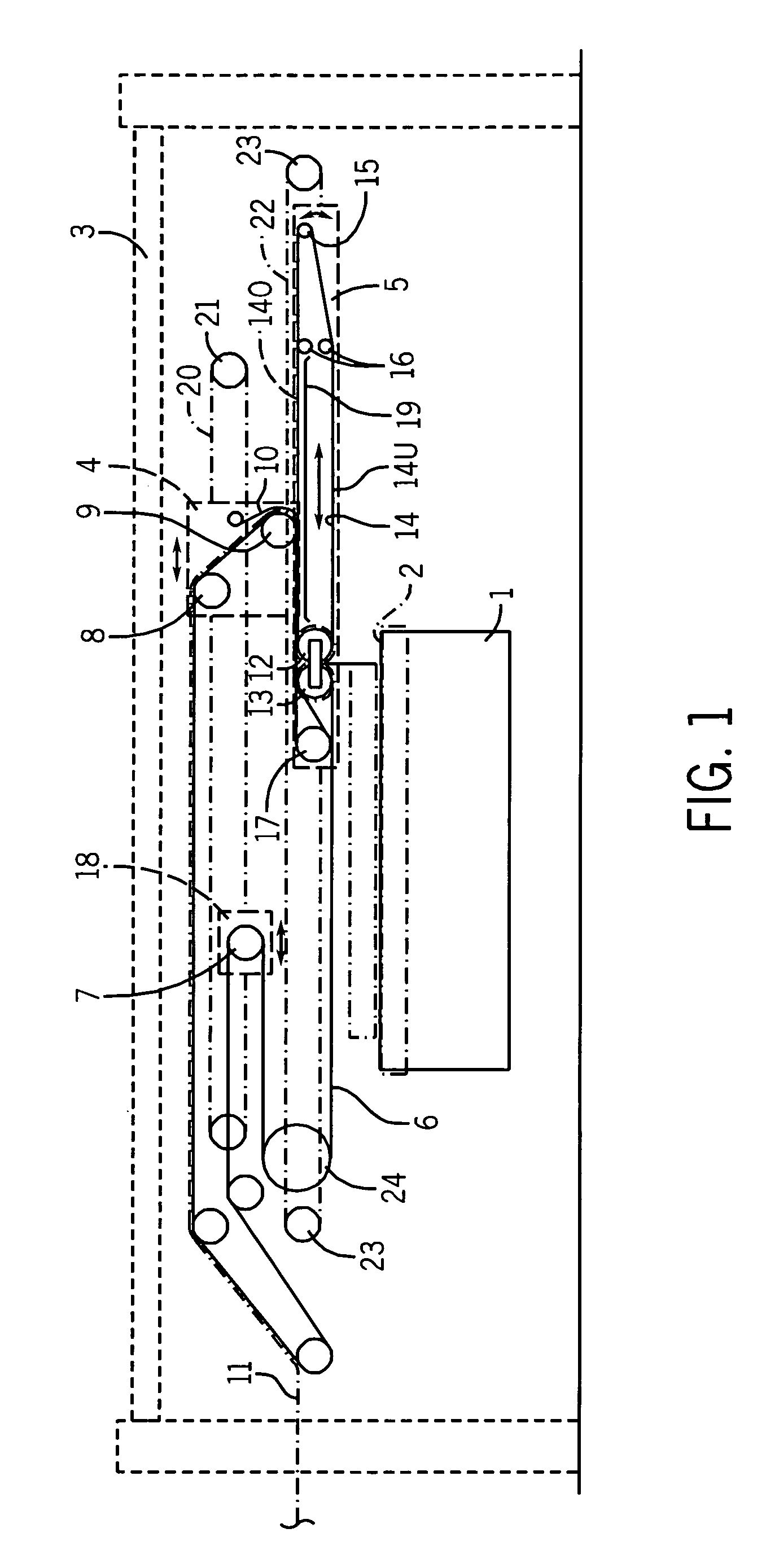
[0018]The drawing shows a preferred embodiment of the invention. A schematic diagram of a fleece layer is presented, consisting of: an output conveyor belt 2 supported in a lower stand 1, this belt being designed as, for example, a slatted belt, one of its deflecting rollers being indicated schematically; an upper carriage 4, which can travel back and forth in a machine stand 3 (illustrated schematically) transversely to the transport direction of the output conveyor belt 2; and a laying carriage 5, which can travel back and forth underneath the upper carriage, also transversely to the output conveyor belt 2.

[0019]A web-carrying conveyor belt, called the web entrance conveyor belt 6 in the following to distinguish it from the other belts, travels through the upper carriage 4 and the laying carriage 5, passing over several deflecting rollers supported in the machine stand 3, some of which are stationary deflecting rollers, and one of which is a belt-tensioning roller 7, which is moun...


PUM

PropertyMeasurementUnit
distanceaaaaaaaaaa
lengthaaaaaaaaaa
heightaaaaaaaaaa

Abstract

A fleece-laying apparatus with an upper carriage (4) and a laying carriage (5) which move above an output conveyor belt (2) transversely to the transport direction of that belt to lay a card web (11) supplied to the fleece layer in partially overlapping layers on an output conveyor belt (2), an endless card web conveyor belt (14) traveling exclusively in the laying carriage (5) wraps around at least one first laying roller (12) in the laying carriage (5). The belt has upper and lower strands (14o, 14u), which extend between the first laying roller (12) and a deflecting roller (15), which is supported in the laying carriage a certain distance away from the laying roller and around which the belt partially wraps. The lower strand (14u) of the web conveyor belt (14) traveling around exclusively in the laying carriage (5) passes only a very short distance away from the output conveyor belt (2), and its upper strand (14o), namely, a section of the upper strand adjacent to the laying gap, supports a length of the card web (11) to be laid from underneath. This length of the card web (11) is covered by the opposing section of another traveling card web guide belt (6).

Description

CROSS REFERENCE TO RELATED APPLICATION[0001]This application claims priority to European patent application EP 07 006 704.6, filed Mar. 30, 2007.FIELD OF THE INVENTION[0002]The invention pertains to a fleece-laying apparatus, such apparatus sometimes being referred to herein as a “fleece layer.” The invention is a fleece-laying apparatus having an upper carriage and a laying carriage which are guided in a machine stand so as to move above, and transversely with respect to, the direction of movement of an output conveyor belt traveling around in the stand, and further having conveyor belts which enclose sandwich-like the card web to be laid on its way from a web entrance to a laying gap so that the card web supplied to the fleece layer can be deposited in partially overlapping layers on the output conveyor belt.BACKGROUND[0003]A fleece layer of the previously described type is known from EP 0 865 521 B1, in which a first card web conveyor belt supplying the card web is routed both th...

Claims


Application Information

Patent Timeline
Patent Type & Authority Patents(United States)
IPC IPC(8): D01G25/00
CPCD01G25/00
Inventor DILO, JOHANN P.
Owner DILO MASCHF OSKAR
Learn More