Brushless electric machine with stator with cascaded end loops

a brushless electric machine and cascade technology, applied in the direction of dynamo-electric machines, synchronous generators, magnetic circuit shapes/forms/construction, etc., can solve the problems of increasing electric load for vehicles, shrinking the overall package size of electrical machines, and insufficient magnetic circuits for conventional brushless electric machine components to achieve higher power density

Active Publication Date: 2010-03-30
BORGWARNER INC
View PDF20 Cites 14 Cited by
  • Summary
  • Abstract
  • Description
  • Claims
  • Application Information

AI Technical Summary

Problems solved by technology

Furthermore, electrical loads for vehicles continue to escalate while, at the same time, the overall package size available for the electrical machine continues to shrink.
Conventional brushless electric machine components lack a sufficient magnetic circuit to achieve higher power densities and require expensive drive end bearings due to their support system.
In addition, they do not have internal cooling needed to supply electricity at these higher demands and therefore have larger package sizes.

Method used


Image

  • Brushless electric machine with stator with cascaded end loops
  • Brushless electric machine with stator with cascaded end loops
  • Brushless electric machine with stator with cascaded end loops

Examples


Embodiment Construction

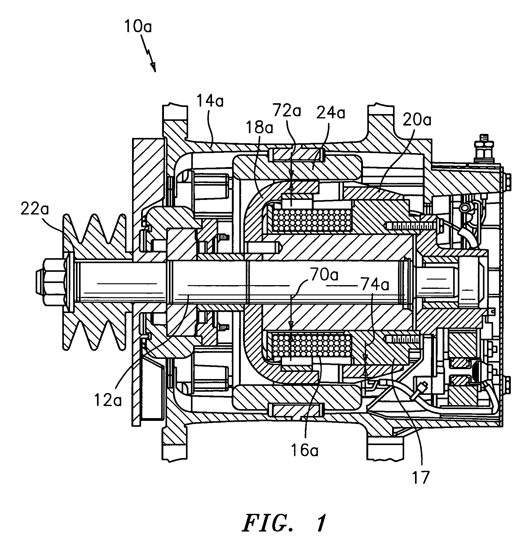
[0023]FIG. 1 illustrates a cross-section view of a brushless electric machine 10a. The brushless electric machine 10a includes a rotatable shaft 12a supported within a housing 14a. A field coil 16a is wound over a spool 17 that is attached to the housing 14a and a first pole segment 18a rotatable with the shaft 12a, and a second pole segment 20a (also rotatable with the shaft 12a) cantilevered from the first pole segment 18a. Additionally, a pulley 22a is attached to a portion of the shaft 12a projecting through the housing 14a. A stator 24a, attached to the housing 14a, surrounds the pole segments 18a and 20a. The stator 24a will be described in great detail with reference to FIGS. 5-13.

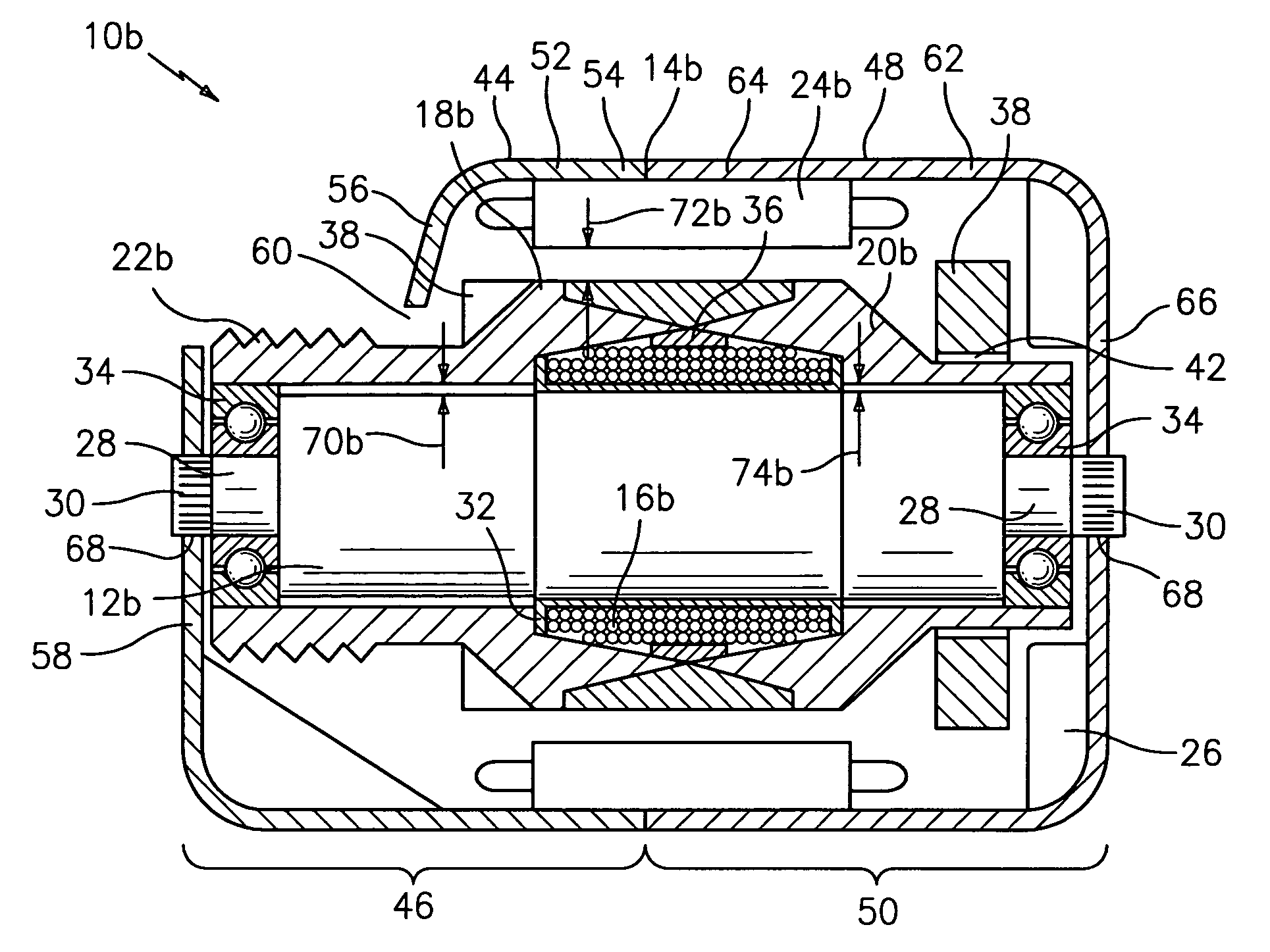
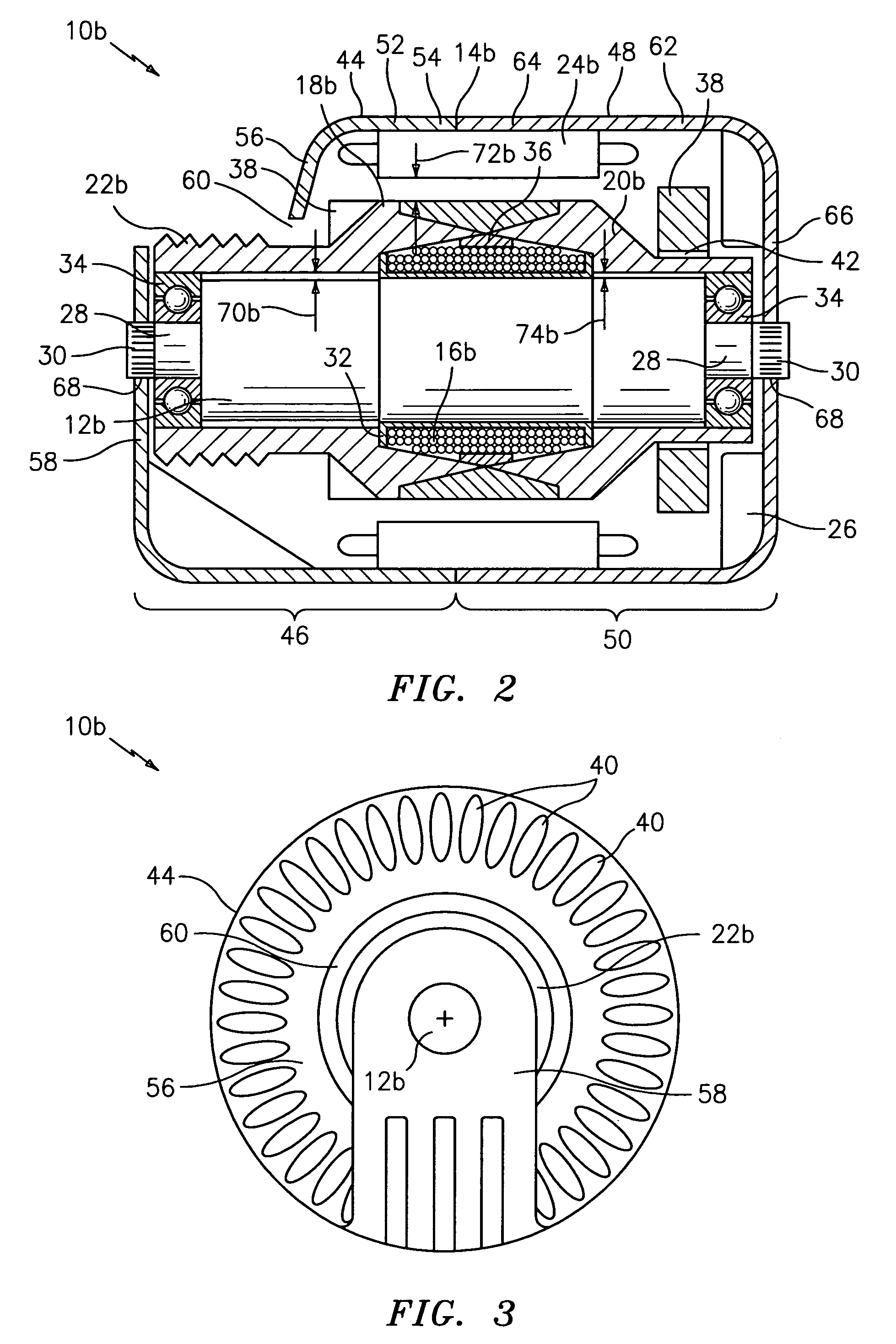
[0024]Referring to FIGS. 2 and 3, an exemplary embodiment of a brushless electric machine 10b that, for example, in one embodiment can be used as an automobile alternator, is illustrated. The brushless electric machine 10b includes a stationary shaft 12b mounted inside a housing 14b. A field coil 16...


PUM


Abstract

Disclosed herein is a brushless electric machine comprising, a housing, a stationary field coil, a shaft, a bearing, a pole segment, and a stator. The stator including a core having a plurality of core slots that extend between a first and a second end of the stator core. The stator also including a winding with a plurality of phases, each of the phases having at least one conductor having a plurality of substantially straight segments disposed in the core slots. The straight segments are alternately connected at the first and the second ends of the stator core by a plurality of end loop segments. A section of at least one of the conductors including three consecutive end loop segments and two straight segments, is formed from a single continuous conductor, and one of the core slots houses a plurality of the straight segments arranged in at least one radial row.

Description

CROSS REFERENCE TO RELATED APPLICATIONS[0001]This application is a continuation-in-part application of U.S. patent application Ser. No. 11 / 394,258 filed Mar. 30, 2006 the entire contents of which are incorporated herein by reference.BACKGROUND OF THE INVENTION[0002]Brushless electric machines for generating electricity are found in many motor vehicles today. These electric machines, also referred to as alternators, produce electricity necessary to power vehicle accessories, as well as to charge a vehicle's battery. Electric machines must also provide the capability to produce electricity in sufficient quantities to power a vehicle's electrical system in a manner that is compatible with the vehicle electrical components. Furthermore, electrical loads for vehicles continue to escalate while, at the same time, the overall package size available for the electrical machine continues to shrink.[0003]Conventional brushless electric machine components lack a sufficient magnetic circuit to a...

Claims


Application Information

Patent Timeline
Patent Type & Authority Patents(United States)
IPC IPC(8): H02K19/00
CPCH02K19/24H02K19/103
Inventor NEET, KIRKYORK, MICHAEL T.BRADFIELD, MICHAEL
Owner BORGWARNER INC
Why Eureka
Try Eureka