
Method and apparatus for determining comfortable footbed shapes

a footbed and comfortable technology, applied in the field of footbed comfort measurement, can solve the problems of imbalance, low use of natural foot shape, and inability to accurately determine the comfort level of the footbed, so as to eliminate imbalance and evaluate the comfort level

Active Publication Date: 2010-03-30
THE HONG KONG UNIV OF SCI & TECH
View PDF18 Cites 9 Cited by
  • Summary
  • Abstract
  • Description
  • Claims
  • Application Information

AI Technical Summary

Benefits of technology

[0046]One advantage of the present invention is that the apparatus can simulate the support surface deformations during different activities such as running, walking or playing other sports. The deformations will be first measured under simulated loading conditions with a compression tester and then those deformations can be incorporated using the mechanisms in the said apparatus so that the comfort levels can be evaluated.
[0047]The stiffness of the supporting surface material can be changed across the width (laterally) using strips of material in the lengthwise direction so that pronation and supination can be controlled and evaluated. Furthermore, the stiffness of the medial and lateral parts of the apparatus can be controlled to obtain similar deformation on the two sides of the foot to eliminate imbalance due to excessive pronation or supination.
[0048]The apparatus and methods of the present invention may also be used to design a custom insole for a shoe wherein the insole material will be deformed while standing on a comfortable supporting surface shape in a desired fashion, depending on the foam or material stiffness of the insole material. The material is placed on the supporting surface of the apparatus and tested in the appropriate simulated configuration of the shoe.
[0049]The required (or ideal or optimal) pressure patterns on the plantar surface of foot may be obtained by varying the shape and stiffness of the material so that a comfortable supporting surface can be generated. The pressure patterns may be obtained using pressure sensors between the foot and the said supporting surface wherein the electrical signals from the sensors are calibrated and displayed as pressure values on a display. The sensors are preferably thin, e.g. paper thin, such that they do not interfere or alter the shape of the foot or the supporting surface. When the shape of the supporting surface is changed, the pressure patterns will change as well. The ideal shape for the required pressure pattern can then be quickly determined using the said apparatus.

Problems solved by technology

In reality, the natural shape of the foot is of little use due to the non-uniform bone and soft tissue structures in the foot.
In other words, the deformations will be different in the different parts of the foot and the neutral shape will not match the varying stiffnesses of the foot.
Methods such as plaster casting too have the same weakness as they give only the neutral shape of the foot.
Optical sensing and contact sensor methods, even though very accurate, have their own weaknesses.
They are ideal for obtaining the neutral shape of the foot but cannot be used to determine the shape inside a shoe or even in situations that simulate a shoe wherein the support surface should have the same parameters corresponding to a shoe.
Transparent material has been used to obtain the plantar shape of the foot but none of the previous methods are able to simulate all the footwear parameters together in order to determine the shape that is comfortable for the foot.
Furthermore, most shoes, especially high-heeled shoes, which have such shapes are not comfortable for a person wearing them.
Even though many different methods have been employed to determine foot shape, there is no robust method that allows the shape that is comfortable to be determined giving due consideration to the lengths, angles, and cushioning properties of the footbed surface.

Method used


Image

  • Method and apparatus for determining comfortable footbed shapes
  • Method and apparatus for determining comfortable footbed shapes
  • Method and apparatus for determining comfortable footbed shapes

Examples


first embodiment

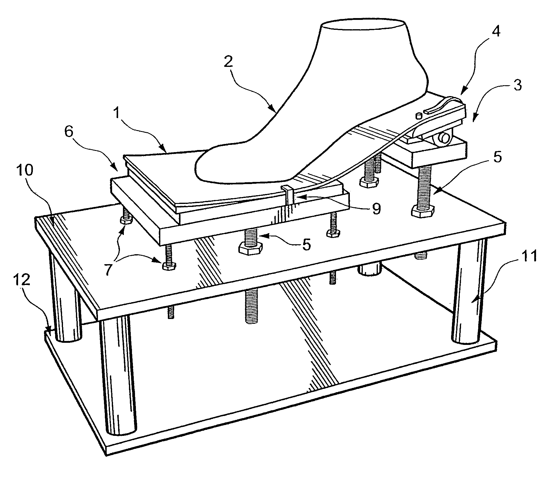
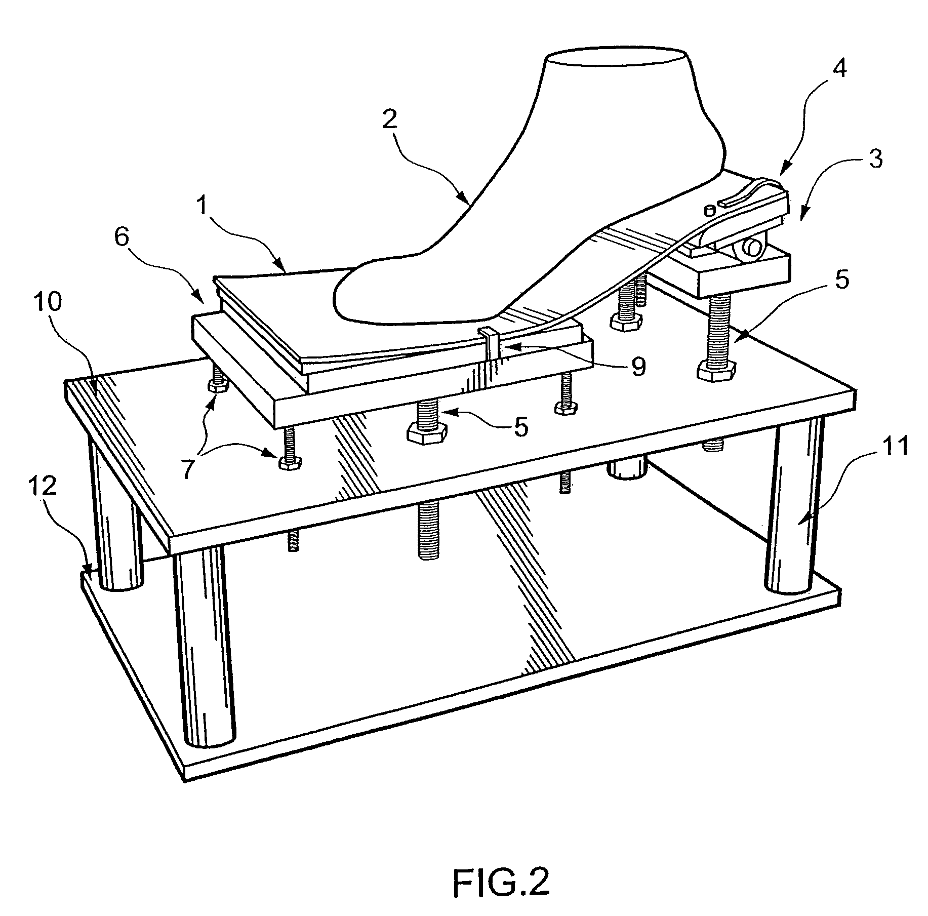
[0072]FIG. 2 and FIG. 3, illustrate an apparatus for determining footbed shapes that are comfortable when worn. The apparatus comprises different surfaces on which a person can position their foot. It comprises a supporting surface 1, a rear platform 3 for supporting the rear of a foot, and a front platform 6 for supporting the front of a foot. The supporting surface 1 is mounted on the front and rear platforms and extends between them. In this embodiment one end of the supporting surface is rigidly fixed to the rear platform 3. The other end of the supporting surface 1 rests on the front platform 6. The middle portion of the supporting surface 1 is for the most part not supported underneath so that the compressive and tensile stresses generated internally due to the bending of the material will allow the shape to change.

[0073]The supporting surface 1 is preferably spring steel. However, any flexible material such as spring steel, polyurethane, or other thermoplastic or thermoset ma...

fourth embodiment

[0105]FIG. 18 shows the present invention, which is an apparatus for determining or measuring a comfortable shape for a neck. It comprises a first platform 3 for supporting the head, a second platform 6 for supporting the shoulders or lower portion of the neck, a middle support member 30 and a flexible supporting surface 1 mounted to and extending between the first and second platforms and middle support member.

[0106]In general functional terms, the parts are as described previously for the apparatus in the first to third embodiments of the present invention. The relative heights of the first and second platforms are adjustable, preferably by adjusting the height of either platform. The second platform 6 has an adjustable angle of inclination so that it may be adjusted to find a comfortable fit for supporting the neck. The middle support member 30 has an adjustable angle and height and may be moved backwards and forwards laterally between the first and second platforms such that it ...

fifth embodiment

[0107]FIG. 19 illustrates the present invention, which is an apparatus for determining and measuring the comfortable shape of a back and may be used to ergonomically design the back support of a chair or sofa. Its parts are similar to the parts in FIG. 18, except the first platform 3 supports the upper back, the second platform 6 supports the lower back and the middle supporting member supports the middle back. The platforms and middle supporting member are height adjustable, but in this context ‘height’ means the lateral distance from the back of the chair 40.


PUM


Abstract

A method and apparatus for determining the comfortable footbed shape for a person. The apparatus comprises a rear platform for supporting the rear of a foot, a front platform for supporting a forefoot, the height of at least one of said front and rear platforms being adjustable relative to the height of the other one of said platforms and fixable at a selected height relative to the other platform; and a supporting surface for accommodating the plantar surface of a foot, the supporting surface comprising a length of flexible material fixable mounted to and extending between said front and rear platforms. The apparatus can adjust the aforementioned components to various settings with a view to determining the plantar foot shape and the perceived comfort in any chosen posture.

Description

CROSS-REFERENCE TO RELATED APPLICATIONS[0001]This application claims benefit of U.S. Provisional Application Ser. No. 60 / 920,746, filed Mar. 30, 2007.FIELD OF THE INVENTION[0002]The present invention relates to an apparatus that can be used for the determination and measurement of footbed shapes that are comfortable. It also relates to a system for obtaining the complete shape of a foot when placed on a simulated footbed. The shape or shapes obtained by the apparatus, correspond to different surfaces and can thereafter be used to make insoles or customized shoes that are comfortable to wear.BACKGROUND OF THE INVENTION[0003]Many methods or devices are used to obtain the plantar shape of the foot. These include molding the foot shape on a malleable material, plaster casting, optical sensing, contact measurement with sensors and so on. When a force is applied on a malleable material with a person's foot, it will deform to the shape of the footprint, which can thereafter be used to make...

Claims


Application Information

Patent Timeline
Patent Type & Authority Patents(United States)
IPC IPC(8): A61B5/103
CPCA61B5/1074
Inventor GOONETILLEKE, RAVINDRA STEPHENWITANA, CHANNA PATUWATHA
Owner THE HONG KONG UNIV OF SCI & TECH
Learn More