Non-linear equalizer in a coherent optical receiver

a technology of optical receiver and equalizer, applied in the field of optical communication networks, can solve the problems of undesirable increase in the bit error rate (ber) of the recovered symbol values x(n) and y(n)

Active Publication Date: 2010-03-23
CIENA CORP
View PDF24 Cites 59 Cited by
  • Summary
  • Abstract
  • Description
  • Claims
  • Application Information

AI Technical Summary

Problems solved by technology

A limitation of this system, however, is that in severely impaired environments, the bit error rate (BER) of the recovered symbol values X(n) and Y(n) may be undesirably increased by residual Inter Symbol Interference (ISI) and DC offset in the rotated symbol estimates X′(n) e−jk(n) and Y′ (n)e−jk(n).

Method used


Image

  • Non-linear equalizer in a coherent optical receiver
  • Non-linear equalizer in a coherent optical receiver
  • Non-linear equalizer in a coherent optical receiver

Examples


Embodiment Construction

[0028]The present invention provides methods and techniques for compensation of non-linear impairments in a receiver unit of an optical network. Embodiments of the present invention are described below, by way of example only, with reference to FIGS. 3-11.

[0029]In general, the present invention provides a system in which compensation of residual ISI and DC offset is performed by digitally processing symbol value decisions generated by the carrier recovery block 28. FIG. 3 schematically illustrates a representative system implementing methods of the present invention.

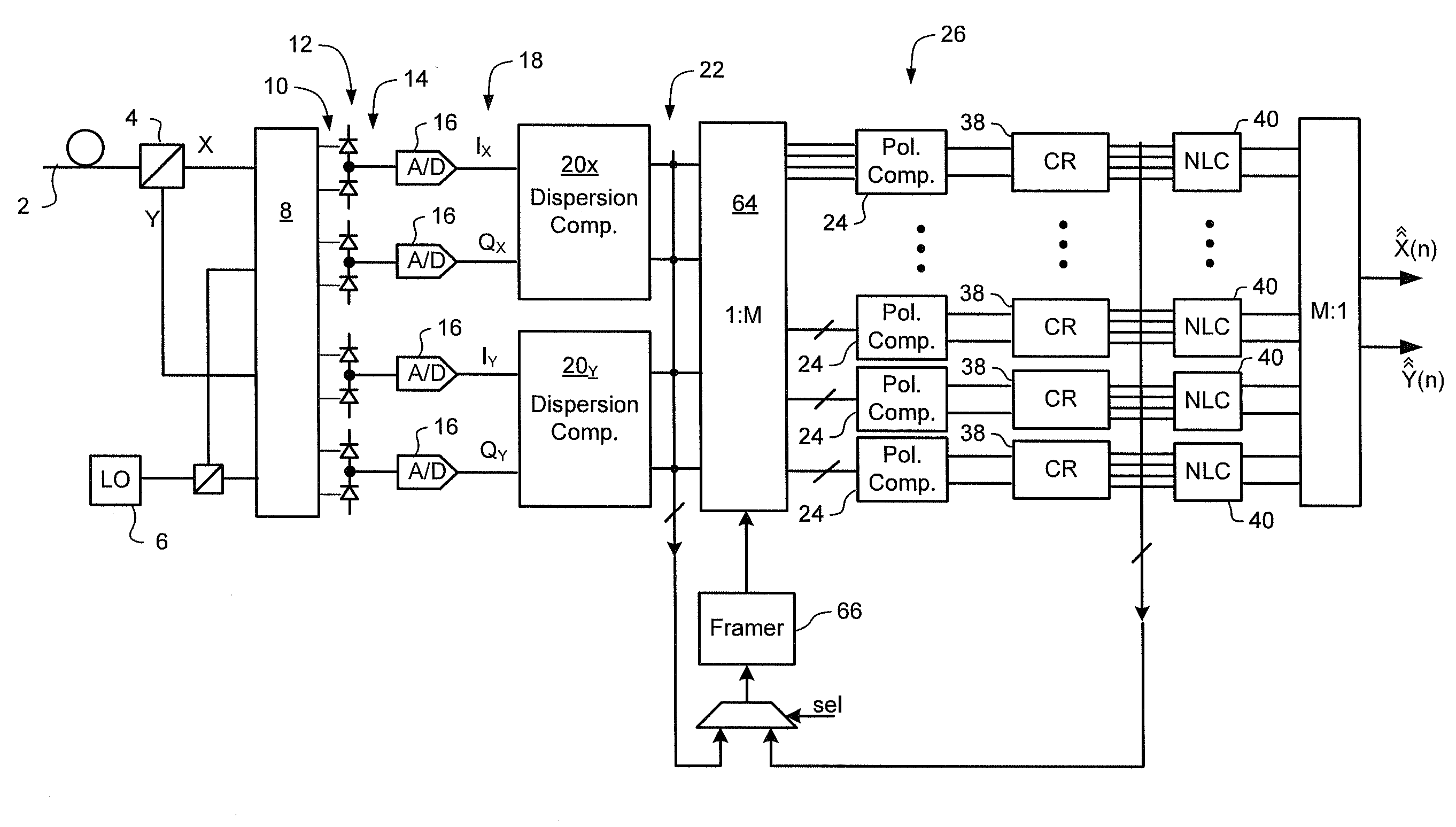
[0030]As may be seen in FIG. 3, a preferred system in accordance with the present invention comprises a carrier recovery block 38 and a non-linear compensator (NLC) 40 connected in series. Preferably, the carrier recovery block 38 is virtually identical to that of FIG. 2, except that, instead of recovered symbol values 28 X(n), Y(n), the carrier recovery block 38 outputs respective hard and soft symbol value decisions fo...


PUM


Abstract

A method of recovering a most likely value of each symbol transmitted through an optical communications network using a high speed optical signal. A stream of multi-bit digital samples of the optical signal is processed to generate a respective multi-bit estimate X′(n) of each transmitted symbol. A first function is applied to each symbol estimate X′(n) to generate a corresponding soft decision value {tilde over (X)}(n). Each soft decision value {tilde over (X)}(n) is processed to generate a corresponding hard decision value. {circumflex over (X)}(n) having an ideal amplitude and phase. A plurality of successive soft decision values and hard decision values are processed to determine a second function, which is applied to each soft decision value {tilde over (X)}(n) to generate a most likely symbol value {circumflex over ({circumflex over (X)}(n).

Description

CROSS-REFERENCE TO RELATED APPLICATIONS[0001]This application claims benefit under 35 U.S.C. 119(e) from U.S. Provisional Patent Application Ser. No. 60 / 728,751, entitled Automatic Gain Control, which was filed on Oct. 21, 2005.TECHNICAL FIELD[0002]The present invention relates to optical communications networks, and in particular to a non-linear equalizer in a coherent optical receiver.BACKGROUND OF THE INVENTION[0003]Optical signals received through conventional optical links are typically distorted by significant amounts of chromatic dispersion (CD) and polarization dependent impairments such as Polarization Mode Dispersion (PMD), polarization angle changes and polarization dependent loss (PDL). Chromatic dispersion (CD) on the order of 30,000 ps / nm, and polarization rotation transients at rates of 105 Hz are commonly encountered. Various methods and systems intended to address some of these limitations are known in the art.[0004]FIG. 1 schematically illustrates a representative ...

Claims


Application Information

Patent Timeline
Patent Type & Authority Patents(United States)
IPC IPC(8): H04B10/06H04L27/06
CPCH04B10/60H04B10/61H04L7/0075H04B10/6165H04B10/6162H04L7/0004
Inventor ROBERTS, KIM B.BONTU, CHANDRAWU, KUANG TSANSUN, HAN
Owner CIENA CORP
Why Eureka
Try Eureka