Printing device, printing device control program and method, and printing data generation device, program, and method

a printing device and control program technology, applied in the direction of instruments, visual presentation, computing, etc., can solve the problems of ink deflection, printing head manufacturing deviation, and drawing a longer printing time compared with other types of printing devices such as electrophotographic laser printers or others

Inactive Publication Date: 2010-03-23
SEIKO EPSON CORP
View PDF17 Cites 2 Cited by
  • Summary
  • Abstract
  • Description
  • Claims
  • Application Information

AI Technical Summary

Benefits of technology

[0022]An advantage of some aspects of the invention is to provide a printing device, a printing device control program and method, and a printing data generation device, program, and method, all of which are newly developed and capable of stopping image degradation or making image degradation less conspicuous that is caused by a banding problem resulted from ink deflection.

Problems solved by technology

There is a problem with such an ink jet printer of a type performing printing with the printing head reciprocating on the carriage in the direction perpendicular to the printing paper.
This results in a drawback of a longer printing time compared with other types of printing device such as electrophotographic laser printers or others, e.g., copying machines.
The issue with such an ink jet printer is the manufacturing deviation observed in the printing head that serves an essential role for the printer.
In such a configuration, the nozzle may be partially misaligned so that the ink discharge direction is incorrectly angled, or the nozzles may not be correctly disposed as they are expected to be so that the nozzles resultantly fail in forming dots at their ideal positions, i.e., causes so-called ink deflection.
As a result, an image part printed by such a faulty nozzle suffers a printing failure, i.e., so-called banding (streaking) problem, resultantly reducing the printing quality considerably.
When the amount of ink coming from any of the nozzles is not ideal and is a lot, the part for the nozzle suffers from dark streaks, and when the amount of ink is little, the part suffers from white streaks.
Such a banding problem is often observed in “line head printers” in which a printing head or a printing medium is fixed, i.e., printing with a single path, compared with the above-described “multi-path printers” (serial printers).
However, from the perspective of manufacturing cost, the technology, or others, it is found difficult to provide a printing head perfectly free from the banding problem.
In consideration thereof, such technologies are not suitable for printing required to be high in image quality and printing quality as color photograph printing.
Another issue is with the technology of allocating information about any discharge-faulty nozzles to right and left thereof to prevent white streaks in parts high in density.
If this technology is applied to solve the above-described ink deflection problem, white streaks are actually reduced but the banding problem still remains unsolved in parts high in density.
The related art of Patent Document 3 causes no problem with printing subjects if they are filled-in images, but cannot be used if printing subjects are of halftone.
However, if with an image of many colors, i.e., one color next to another, the technology also fails to solve the problem of hue change in the image.
The related art of Patent Document 4 also raises an issue of complicating the feeding-back process that is expected to be appropriately executed against the problem of not deriving ideal dot formation details, and such an issue is difficult to solve.
The expression of “banding problem” means a printing failure of white and dark streaks observed together in the printing result.
This is resulted from so-called ink deflection due to nozzles varying in dot formation positions, and being not at their ideal positions.
The “banding problem” also means a printing failure of white and dark streaks observed in the printing result due to ink discharge failures, e.g., no ink is discharged from the nozzles.
This favorably reduces degradation of printing quality such as white and dark streaks as a result of the banding problem.
These streaks are those caused by a banding problem, which is often observed in line head printing heads that complete printing with a single scan, i.e., a single path.
The above-described banding problem is pretty common with printing heads of line head type, but printing heads of multi-path type are not yet free from such a problem.
These streaks are those caused by a banding problem, which is observed in multi-path printing heads.

Method used


Image

  • Printing device, printing device control program and method, and printing data generation device, program, and method
  • Printing device, printing device control program and method, and printing data generation device, program, and method
  • Printing device, printing device control program and method, and printing data generation device, program, and method

Examples


first embodiment

[0289]Described below is a first embodiment of the invention referring to the accompanying drawings. FIGS. 1 to 11B are all a diagram showing the first embodiment of the invention, i.e., a printing device, a printing device control program and method, and a printing data generation device, program, and method.

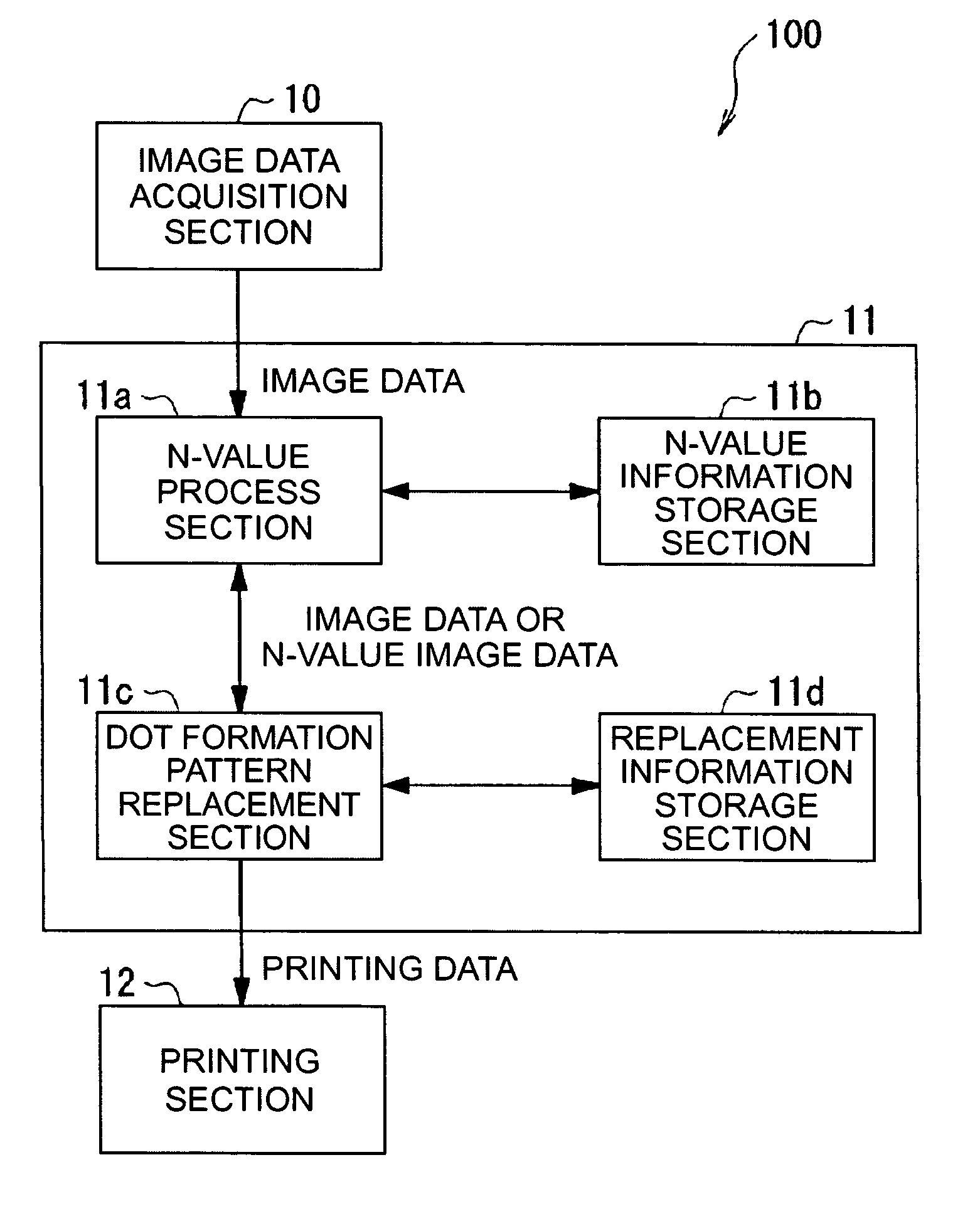
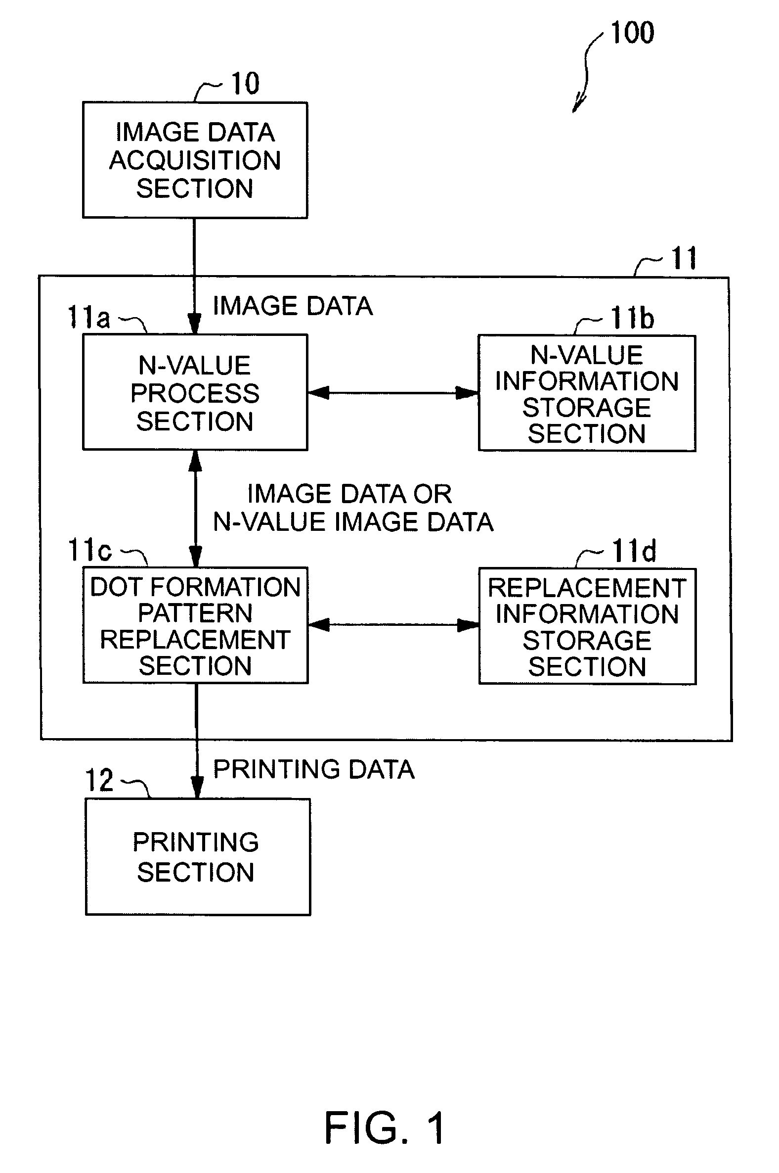
[0290]Described first is the configuration of a printing device 100 of the invention by referring to FIG. 1. FIG. 1 is a block diagram showing the configuration of the printing device 100 of the invention.

[0291]As shown in FIG. 1, the printing device 100 is of a line-head type, configured to include: an image data acquisition section 10; a printing data generation section 11; and a printing section 12. More specifically, the image data acquisition section 10 acquires image data from any external devices, storage devices, or others. The image data is the one configuring any predetermined image. The printing data generation section 11 generates printing data for use of printing i...

second embodiment

[0357]Described next is a second embodiment of the invention by referring to the accompanying drawings. FIGS. 12 to 16B are all a diagram showing the second embodiment of the invention, i.e., a printing device, a printing device control program and method, and a printing data generation device, program, and method.

[0358]In the second embodiment, the printing device and the computer system both are in the similar configuration as those in the first embodiment shown in FIGS. 1 and 2. The second embodiment is different from the first embodiment in the respect that the printing data generation process in step S104 of FIG. 5 is replaced with the process of FIG. 12.

[0359]Although the printing data generation process of FIG. 12 is the same as that of the first embodiment in principle, differences lie in the following respects. That is, a replacement process is executed at the same time as an N-value process, and banding avoiding dot formation pattern data for use of replacement based on no...

third embodiment

[0401]Described next is a third embodiment of the invention by referring to the accompanying drawings. FIGS. 17 to 19 are all a diagram showing the third embodiment of the invention, i.e., a printing device, a printing device control program and method, and a printing data generation device, program, and method.

[0402]In the third embodiment, the printing device and the computer system both are in the similar configuration as those in the first embodiment shown in FIGS. 1 and 2. The third embodiment is different from the first embodiment in the respect that the printing data generation process in step S104 of FIG. 5 is replaced with the process of FIG. 17.

[0403]Although the printing data generation process of FIG. 17 is the same as that of the first and second embodiments in principle, differences lie in the following respects. That is, a replacement process is executed after an N-value process, and banding avoiding dot formation pattern data for use of replacement based on nozzle in...


PUM


Abstract

A printing device that prints an image by forming a dot formation pattern on a printing medium in accordance with image data of a printing object using a printing head that includes a plurality of nozzles each being capable of forming dots to the printing medium. The printing device includes: an image data acquisition unit that acquires the image data showing pixel values of M (M≧2) for the image; a dot formation pattern data storage unit that stores banding avoiding dot formation pattern data for forming a dot formation pattern for banding avoidance use that includes the dots each being correlated to information about any of the nozzles relating to a banding problem; a printing data generation unit that generates printing data as a result of converting the image data into dot formation pattern data for use of forming a printing image of the image data on the printing medium; and a printing unit that prints, based on the printing data, the printing image of the image data onto the printing medium using the printing head. In the printing device, based on the image data, and the dot formation pattern data stored in the dot formation pattern data storage unit, the printing data generation unit generates the printing data by replacing data in the image data about the dots taken charge by the nozzle relating to the banding problem with the banding avoiding dot formation pattern data for the nozzle.

Description

RELATED APPLICATIONS[0001]This application claims priority to Japanese Patent Application Nos. 2005-016490 filed Jan. 25, 2005 and 2005-282162 filed Sep. 28, 2005 which are hereby expressly incorporated by reference herein in their entirety.BACKGROUND[0002]1. Technical Field[0003]The present invention relates to a printing device for use with printers of facsimile machines, copying machines, OA equipment, and others, and a printing device control program and method. More specifically, the invention relates to a printing device suitable for printing with a so-called ink jet technology, and capable of text and image rendering onto a printing paper (printing material) through discharge of liquid ink particles of various colors, a control program and method for such a printing device, and a printing data generation device, program, and method.[0004]2. Related Art[0005]Described below is a printing device, specifically a printer of an ink jet type (hereinafter, referred to as “ink jet pr...

Claims


Application Information

Patent Timeline
Patent Type & Authority Patents(United States)
IPC IPC(8): B41J2/205B41J2/15B41J2/21B41J29/38B41J29/393
CPCG06K15/102G06K2215/0085
Inventor ARAZAKI, SHINICHI
Owner SEIKO EPSON CORP
Why Eureka
Try Eureka