
Apparatus, method, and medium for adaptively setting reference sensing boundary of touch sensor

a technology of touch sensor and reference value, applied in the sensing technology of touch sensor, can solve the problems of inability to reduce, change the reference value, and increase the cost and time, and achieve the effect of enhancing the operation reliability of the touch sensor

Inactive Publication Date: 2010-03-23
SAMSUNG ELECTRONICS CO LTD
View PDF12 Cites 2 Cited by
  • Summary
  • Abstract
  • Description
  • Claims
  • Application Information

AI Technical Summary

Benefits of technology

The present invention provides an apparatus, method, and medium for adaptively setting a reference sensing boundary and adaptively changing the sensitivity and threshold of a touch sensor. This allows for enhanced operational reliability of the touch sensor without user intervention. The apparatus includes a reference sensing boundary setting unit, a determination unit, and an output unit. The method includes setting the reference sensing boundary, determining if a measured value is within the reference sensing boundary, and outputting the measured value if it is. The computer readable medium stores computer instructions for implementing the methods.

Problems solved by technology

Accordingly, in the development and mass-production of switches, cost and time increase.
Even after a reference value is set, the conditions under which the reference value was set change with respect to changes in the surrounding conditions or changes in the environment, which causes difficulties in the maintenance and modification of the reference value.
However, according to the above technology, when a user's hand is wet or a touch sensor is used in a humid environment, the reference value changes and cannot be lowered until the system is completely reset.
Accordingly, changes in capacitance due to actual contact with a human body cannot be sensed and the touch sensor is not suitable to be used for a portable device.

Method used


Image

  • Apparatus, method, and medium for adaptively setting reference sensing boundary of touch sensor
  • Apparatus, method, and medium for adaptively setting reference sensing boundary of touch sensor
  • Apparatus, method, and medium for adaptively setting reference sensing boundary of touch sensor

Examples


Embodiment Construction

[0025]Reference will now be made in detail to exemplary embodiments of the present invention, examples of which are illustrated in the accompanying drawings, wherein like reference numerals refer to the like elements throughout. Exemplary embodiments are described below to explain the present invention by referring to the figures.

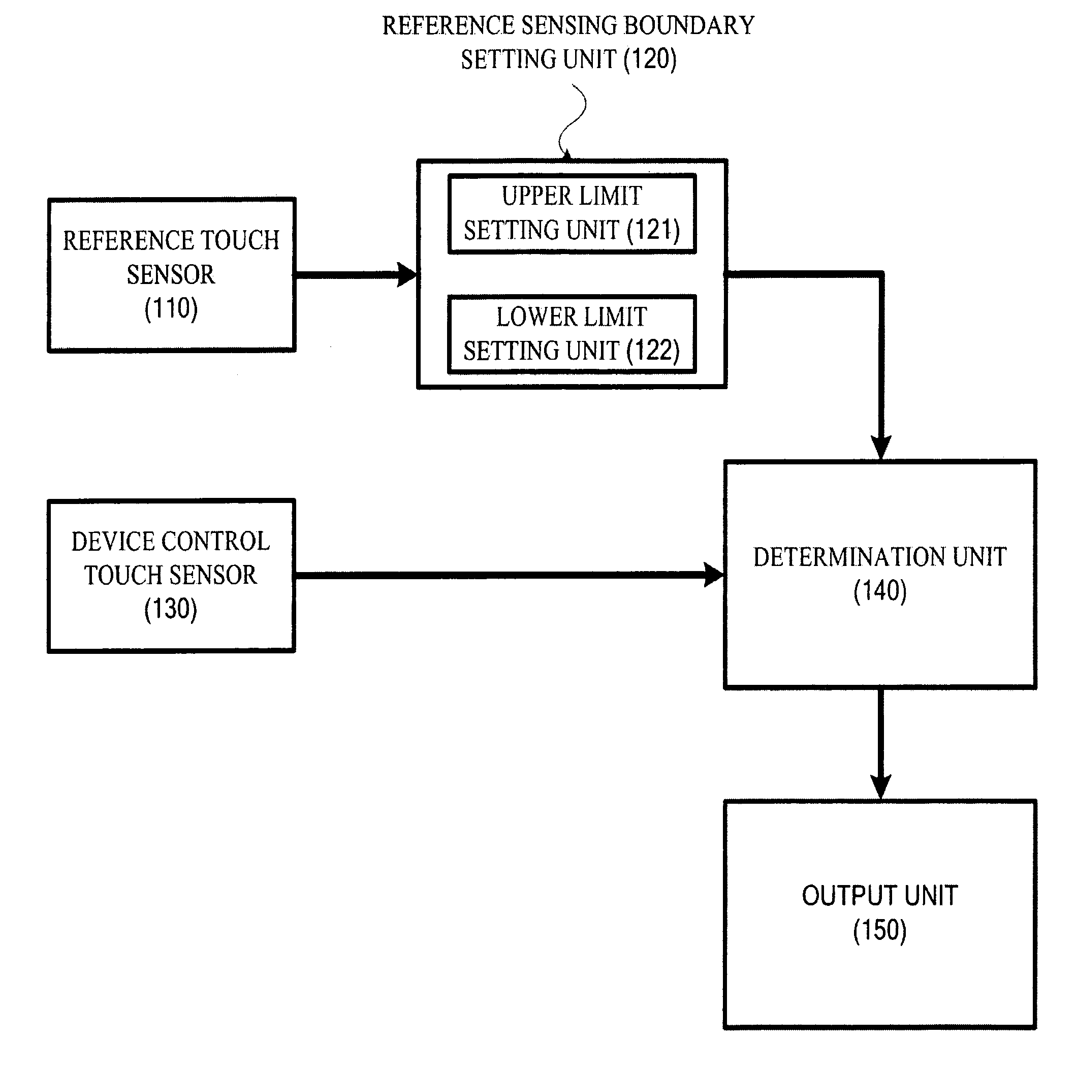
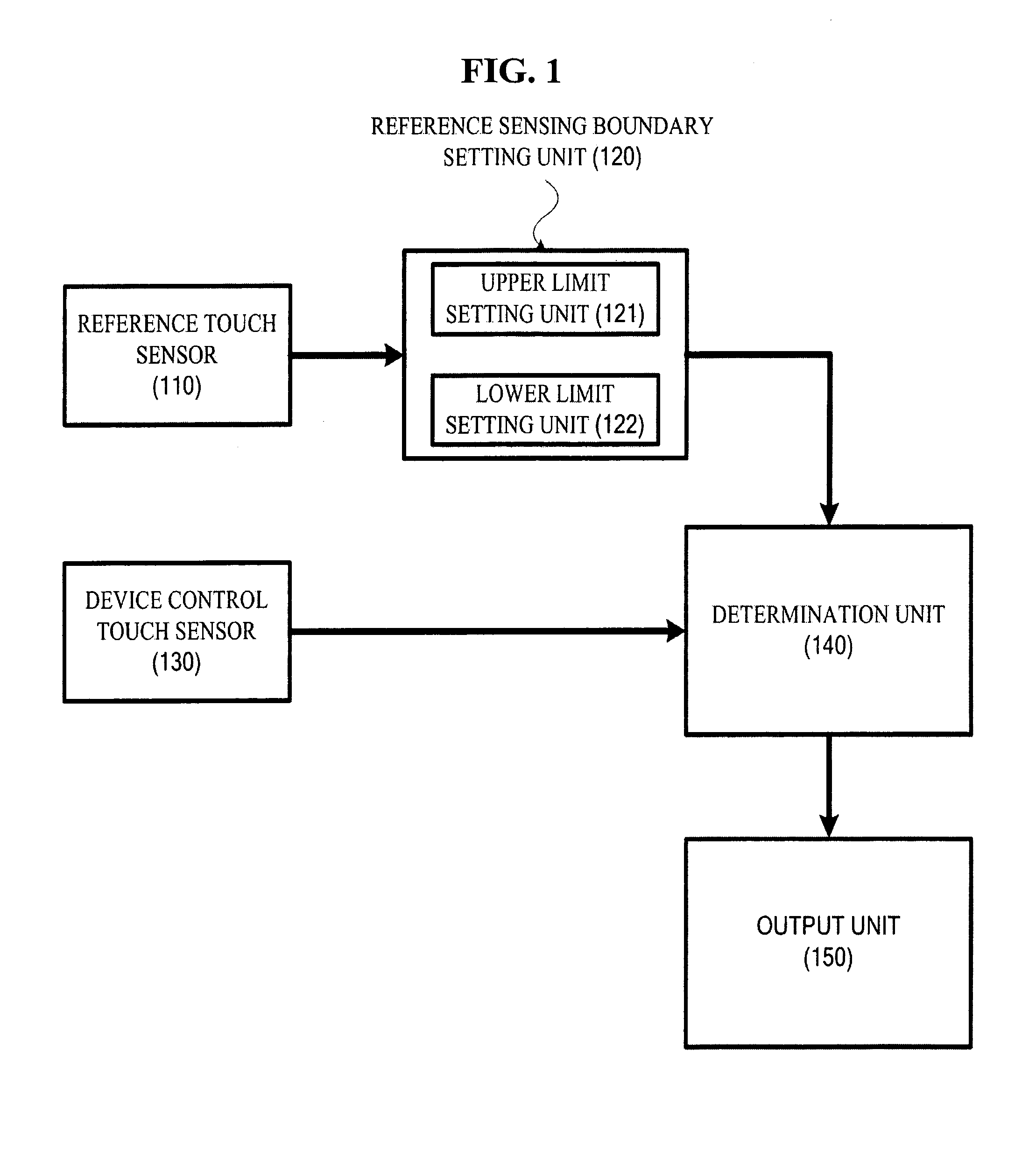
[0026]FIG. 1 is a block diagram illustrating an entire structure of an apparatus for adaptively setting a reference sensing boundary of a touch sensor according to an exemplary embodiment of the present invention. Referring to FIG. 1, the apparatus for adaptively setting a reference sensing boundary of a touch sensor is composed of a reference touch sensor 110, a reference sensing boundary setting unit (reference sensing boundary setter) 120, a device control touch sensor 130, a determination unit (determiner) 140 and an output unit 150. The reference sensing boundary setting unit (reference sensing boundary setter) 120 includes an upper limit setting unit ...


PUM


Abstract

Provided are an apparatus for and method and medium of adaptively setting a reference sensing boundary of a touch sensor. The apparatus for adaptively setting a reference sensing boundary includes a reference sensing boundary setting unit adaptively setting a reference sensing boundary of a capacitance using a signal generated by a reference touch sensor; a determination unit determining whether or not a value measured by a device control touch sensor controlling a device to which the reference touch sensor is attached is within the set reference sensing boundary, by sensing a change in the capacitance; and an output unit outputting the measured value if the determination result indicates that the measured value is within the reference sensing boundary. Accordingly, the reference sensing boundary of the touch sensor is automatically recalculated without a user's intervention and a sensitivity and threshold of the touch sensor are adaptively changed so that the operational reliability of the touch sensor can be enhanced.

Description

CROSS-REFERENCE TO RELATED APPLICATIONS[0001]This application claims priority from Korean Patent Application No. 10-2006-0013687 filed on Feb. 13, 2006 in the Korean Intellectual Property Office, the disclosure of which is incorporated herein by reference in its entirety.BACKGROUND OF THE INVENTION[0002]1. Field of the Invention[0003]The present invention relates to a sensing technology of a touch sensor, and more particularly, to an apparatus for and method and medium of adaptively setting a reference sensing boundary of a touch sensor in which a reference sensing boundary of a touch sensor is set adaptively so that a value measured by the touch sensor is output only when the value is within the set reference sensing boundary.[0004]2. Description of the Related Art[0005]In general, touch type switches are becoming more commonly used than pushbutton type switches in consumer electronic products or liquid crystal display (LCD) monitors. In touch switches, an electrode is disposed ins...

Claims


Application Information

Patent Timeline
Patent Type & Authority Patents(United States)
IPC IPC(8): G01B7/16
CPCH03K17/962H03K2217/94026H01L21/67253
Inventor CHANG, WOOKBANG, WON-CHULPARK, JOON-AHKIM, YEUN-BAE
Owner SAMSUNG ELECTRONICS CO LTD
Learn More