
Anti-collision warning system for marine vehicle and anti-collision analysis method

a marine vehicle and anti-collision technology, applied in traffic control systems, using reradiation, instruments, etc., can solve the problems of high vulnerability of ships, poor control of collision risk, and environmental consequences of collisions,

Inactive Publication Date: 2010-03-16
SEA ON LINE
View PDF20 Cites 16 Cited by
  • Summary
  • Abstract
  • Description
  • Claims
  • Application Information

AI Technical Summary

Problems solved by technology

The risk of collision which is poorly controlled at sea, comes mainly from an insufficiency of the look-out means.
The consequences of these collisions are often serious for the environment when they involve oil tankers or chemical tankers.
In the field of maritime passenger transport, the ships (ferries, roll on / roll off ships, etc.) are highly vulnerable.
In the field of yachting, collisions are also quite frequent.
Collisions at sea mainly result from a lack of look-out.
A human failure is at the origin of 70 to 90% of accidents, either by insufficient vigilance, or negligence of the officers of watch, or by routine and poor assessment of the risk.
Accidents can also result from a lack of qualification, an ignorance of rules, or even from a total incompetence of the officers of watch.
It is also frequent for the number of officers of watch to be insufficient due to a reduction in the crew (maneuvers, maintenance, commercial activity, etc.), resulting in the officers of watch being overworked and overly tired.
These accidents can also result from poor use of the radar system.
Now, this procedure is often poorly applied.
These systems have a high rate of false alarms.
The result is that the alarm device associated with the system is often stopped.
However, the AIS does not take into account the traffic of ships that are not equipped with this system and that are much greater in number.

Method used


Image

  • Anti-collision warning system for marine vehicle and anti-collision analysis method
  • Anti-collision warning system for marine vehicle and anti-collision analysis method
  • Anti-collision warning system for marine vehicle and anti-collision analysis method

Examples


first embodiment

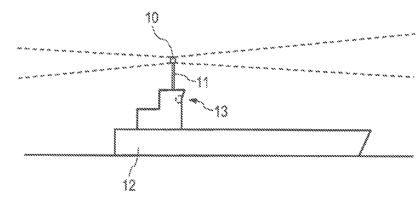
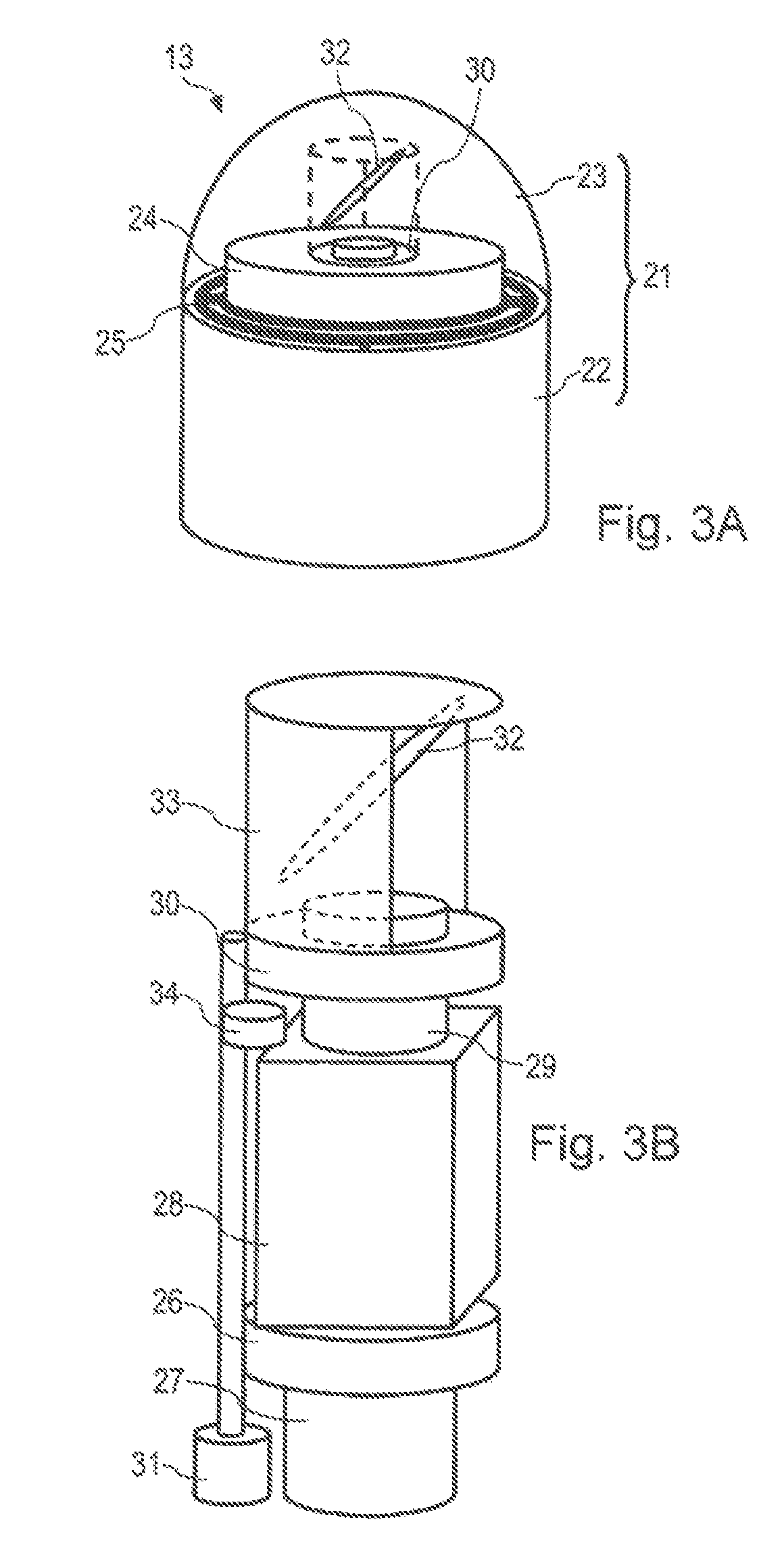
[0052]In the first embodiment shown in FIG. 3A and 3B, the optical sensor 10 comprises a video camera the optical field of which can be oriented to cover the horizon by rotation. The video camera is mounted onto a platform stabilized by a gyroscope. The sensor 10 includes a housing 21 made up of a base 22 used as a stand and a transparent dome shield 23, a stabilized tank 24 mounted onto a stabilization device made up of a gimbal 25 and of a gyro wheel 26 driven by an electric motor 27, a video camera 28 fixed onto the stabilized tank and bearing a lens 29 facing the zenith, and a rotating assembly 30 mounted in the stabilized tank driven by a vertical axis rotation motor 31 placed in the bottom of the stabilized tank, and bearing in its upper part a mirror 32 and a sun screen 33. The 45°-orientation of the mirror enables the optical axis of the mirror 32 to scan a horizontal plane by the rotation of the rotating assembly 30, the rays being reflected by the mirror 32 so as to reach ...

second embodiment

[0059]In a second embodiment shown in FIGS. 4A and 4B, the optical sensor 10 comprises a single-line video camera that can be oriented, mounted onto a fixed stand.

[0060]More precisely, the optical sensor 10 includes a cylindrical housing 41 fixed onto the masts of the ship, a rotating assembly 42 held in the housing 41 by ball bearings 43 and driven by a vertical axis rotation motor 44 placed at the bottom of the housing, the upper part of the rotating assembly comprising a cylindrical protection cover 45 provided with a rectangular window 49 that enables the optic rays to pass through the cover to reach the lens, and a digital video camera 46 fixed onto the rotating assembly 42 and the single-line detecting element 47 of which is offset above the body of the video camera; the detecting element typically comprises from 512 to 8,192 light-sensitive basic cells disposed in a vertical line. The optical sensor also includes a lens 48, having an angular opening typically of 30 to 55°, di...

third embodiment

[0069]In a third embodiment shown in FIGS. 5A and 5B, the optical sensor 10 comprises a set of fixed video cameras. More precisely, the optical sensor 10 includes a housing 61 fixed onto the superstructure of the ship and comprising a glass opening 62, one or more digital video cameras 63 (typically four) fixed onto the housing 61, and one lens 64 for each video camera 63, the set of lenses being disposed in such a way that the areas they scan cover a substantial portion of the horizon (typically 187°). The optical sensor 10 also includes a connection and multiplexing device 65 enabling the images coming from all the video cameras to be processed simultaneously. This device can integrate an integrated circuit card performing part of the image processing.

[0070]In this third embodiment, the resolution of the images is linked to the platform movements of the carrier ship. Typically, on a large ship having a rolling motion limited to + / −10°, using video cameras having a definition of 1,...


PUM


Abstract

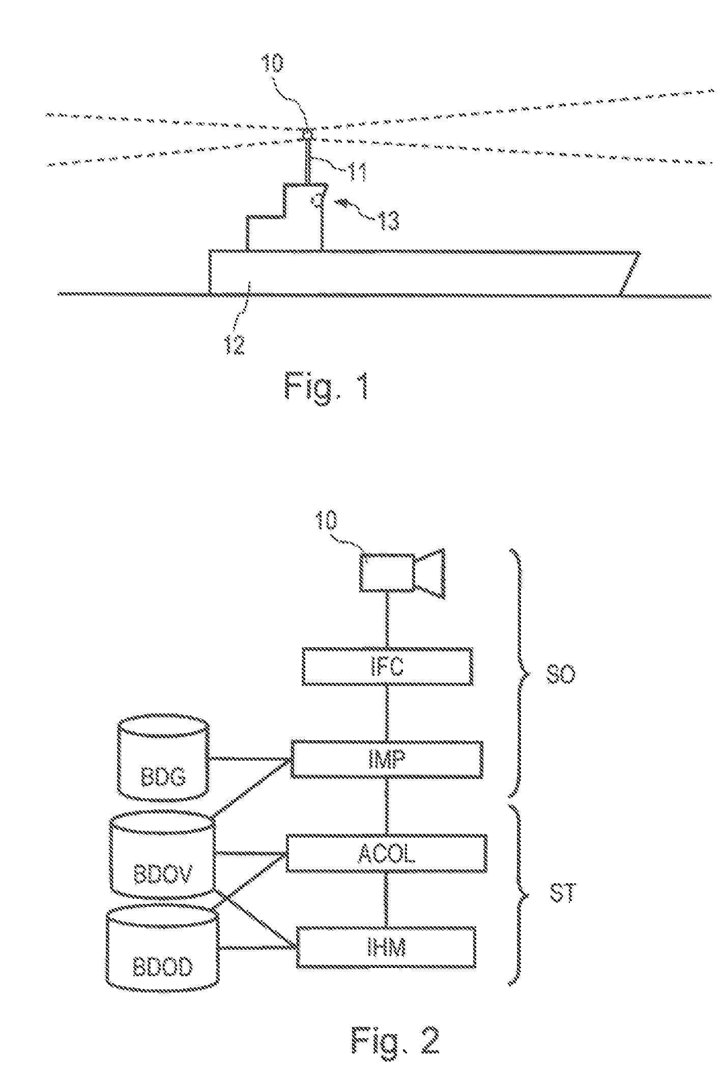
An anti-collision warning system for marine vehicle includes, an optical sensor covering at least partially the horizon of the marine vehicle, image processing means for extracting in real time from each image position information of objects visible on the surface of the sea, and anti-collision analysis means, which periodically calculate the evolution of the position information of each visible object, and which assess a risk of the marine vehicle colliding with each visible object according to the evolution of the position information of the visible object.

Description

CROSS-REFERENCE TO RELATED APPLICATIONS[0001]This application is a Continuation of International Application No. PCT / IB2005 / 002903, filed Sep. 29, 2005, which was published in the French language on Apr. 6, 2006, under International Publication No. WO 2006 / 035305 A2 and the disclosure of which is incorporated herein by reference.BACKGROUND OF THE INVENTION[0002]Embodiments to the present invention relate to an anti-collision warning system for marine vehicle and to an anti-collision analysis method by processing images coming from an omnidirectional optical sensor installed on board a marine vehicle. More particular, embodiments of the present invention apply mainly, but not exclusively, to ships and to naval drones.[0003]In the rest of the description, the marine vehicle considered as an example is a ship.[0004]The risk of collision which is poorly controlled at sea, comes mainly from an insufficiency of the look-out means. In the field of maritime transport, there are 600 collisio...

Claims


Application Information

Patent Timeline
Patent Type & Authority Patents(United States)
IPC IPC(8): G08B23/00G01S17/93
CPCG01S17/93G06T7/00G08G3/02
Inventor WAQUET, PHILIPPE
Owner SEA ON LINE
Learn More