Drive unit
a technology of drive unit and drive shaft, which is applied in the direction of generator/motor, electric/magnetic position measurement, instruments, etc., can solve the problems of increasing the cost and and increasing the size of the drive uni
- Summary
- Abstract
- Description
- Claims
- Application Information
AI Technical Summary
Benefits of technology
Problems solved by technology
Method used
Image


Examples
embodiment 1
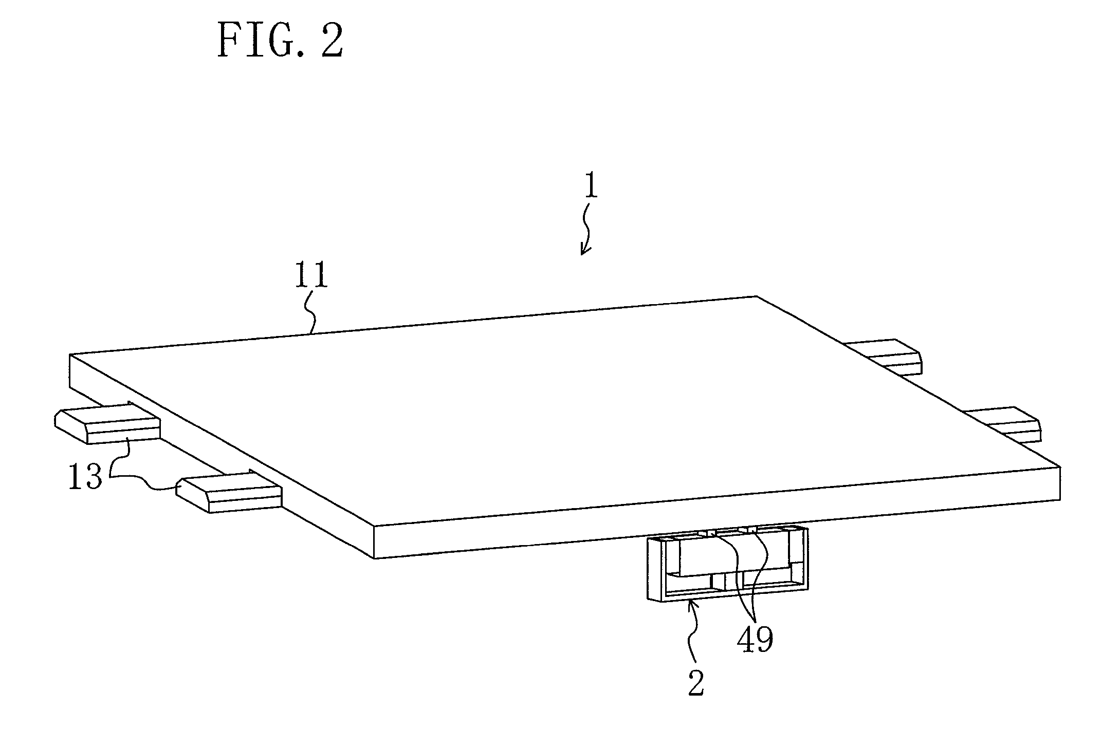
[0031]A drive unit 1 according to an embodiment of the invention includes, as shown in FIGS. 1 and 2, a stage 11, an ultrasonic actuator 2 and a control unit 7 for controlling and driving the ultrasonic actuator 2.
[0032]The stage 11 is slidably attached to guides 13 fixed in parallel with each other to a base (not shown) as a stationary body. That is, the stage 11 is movable in the extending direction of the guides 13 (the extending direction of the guides 13 is the moving direction of the stage 11). The stage 11 is a plate-like member and substantially square-shaped when viewed in plan. The ultrasonic actuator 2 is arranged such that driver elements 49 described later come into contact with the rear surface of the stage 11 (the surface on which the guides 13 are provided). The stage 11 functions as a movable body and the base and the guides 13 function as a stationary body.
[0033]The ultrasonic actuator 2 includes, as shown in FIG. 3, an actuator body 4 which generates vibration, dr...
embodiment 2
[0076]Referring to FIG. 14, a drive unit 201 according to Embodiment 2 of the present invention will be described.
[0077]The drive unit 201 of Embodiment 2 is the same as that of Embodiment 1 except the configuration of an undulating surface 212 formed on a stage 211. The same components as those described in Embodiment 1 will be indicated by the same reference numerals to omit detailed explanation.
[0078]Specifically, the rear surface of the stage 211 of the drive unit 201 is provided with the undulating surface 212 as shown in FIG. 14. The undulating surface 212 include concavities 212a and convexities 212b formed alternately at a certain pitch along the moving direction of the stage 211 and have the same width which is smaller than the interval between the two driver elements 49 and larger than the width of each of the driver elements 49. That is, the driver elements 49 will not be in contact with the same concavity 212a or the same convexity 212b at the same time.
[0079]Even if the...
embodiment 3
[0081]Referring to FIG. 15, a drive unit 301 according to Embodiment 3 of the present invention will be described.
[0082]The drive unit 301 of Embodiment 3 is the same as that of Embodiment 1 except the configuration of an undulating surface 312 formed on a stage 311. The same components as those described in Embodiment 1 will be indicated by the same reference numerals to omit detailed explanation.
[0083]The rear surface of the stage 311 of the drive unit 301 is provided with the undulating surface 312 as shown in FIG. 15. The undulating surface 312 includes undulations of certain unique patterns formed on the stage 311 at certain positions in the moving direction of the stage 311.
[0084]Specifically, a first undulation 312A, a second undulation 312B and a third undulation 312C are formed in first, second and third positions in the moving direction of the stage 311, respectively. These first, second and third positions represent absolute positions in that the corresponding pattern is ...
PUM
 Abstract
Description
Claims
Application Information
 - R&D
- Intellectual Property
- Life Sciences
- Materials
- Tech Scout
- Unparalleled Data Quality
- Higher Quality Content
- 60% Fewer Hallucinations
Browse by: Latest US Patents, China's latest patents, Technical Efficacy Thesaurus, Application Domain, Technology Topic, Popular Technical Reports.
© 2025 PatSnap. All rights reserved.Legal|Privacy policy|Modern Slavery Act Transparency Statement|Sitemap|About US| Contact US: help@patsnap.com