
Spiral/coil wrap stand

Inactive Publication Date: 2010-03-16
LONDO KEVIN C
View PDF17 Cites 11 Cited by
  • Summary
  • Abstract
  • Description
  • Claims
  • Application Information

AI Technical Summary

Benefits of technology

[0010]A secondary objective of the present invention is to provide stand and holder devices, apparatus and methods for wrapping about underlying supports such as tree trunks and tree limbs and poles and pillars and table legs and railing supports, in order to hold and display pots, planters, flowers, plants, bird seed, tables, beverages and food items, that can easily be attached to the underlying supports.
[0011]A third objective of the present invention is to provide stand and holder devices, apparatus and methods for wrapping about underlying supports such as tree trunks and tree limbs and poles and pillars and table legs and railing supports, in order to hold and display pots, planters, flowers, plants, bird seed, tables, beverages and food items and other objects, that does not cause any damage and / or scarring to the underlying supports.
[0013]A fifth objective of the present invention is to provide stand and holder devices, apparatus and methods for wrapping about underlying supports such as tree trunks and tree limbs and poles and pillars and table legs and railing supports, in order to hold and display pots, planters, flowers, plants, bird seed, tables, beverages and food items, that is inexpensive in material coasts and does not require extra labor time to assemble.
[0014]A sixth objective of the present invention is to provide stand and holder devices, apparatus and methods for wrapping about underlying supports such as tree trunks and tree limbs and poles and pillars and table legs and railing supports, in order to hold and display pots, planters, flowers, plants, bird seed, tables, beverages and food items, that is attractive in appearance and adds aesthetically to the surroundings in which it is used.

Problems solved by technology

Many of these stands can require assembly time and be expensive to purchase and assemble, as well as be unsightly and unattractive.
In addition, such stands take up valuable ground space which restricts use and enjoyment of backyards and gardens.
For example, townhouses, and many new homes, have small backyards that do not allow for the display of many planters and pots.
Thus, ground based stands are undesirable.
However, elevating pots and planters has required one to use hooks and other fasteners, such as tight bands and wires and chains (rust, etc.), that can have inherent problems.
For example, fastening the hooks to structures such as porches, and the like, as well as to fences and even trees, requires labor and extra materials such as but not limited to hooks, and other fasteners, that must be carefully mounted.
In addition, such fasteners, that use nails and screws, and / or tight bands, wires, etc., can also cause permanent damage to those supports when they are being attached.
While it may be possible to fix underlying supports such as porch columns and fences, natural supports such as trees, are generally not replaceable and can become permanently scarred and damaged.
Often these hook and band type fasteners form permanent attachments to underlying structures and can not be reusable.
Additionally, many stands can require extensive material cost and time to assemble, and also can result in unsightly and unattractive supports that are not desirable for displaying pots and planters of flowers and plants.
However, these supports are no better than those previously mentioned and do not overcome all the problems with the prior art.

Method used


Image

  • Spiral/coil wrap stand
  • Spiral/coil wrap stand
  • Spiral/coil wrap stand

Examples


embodiment 1

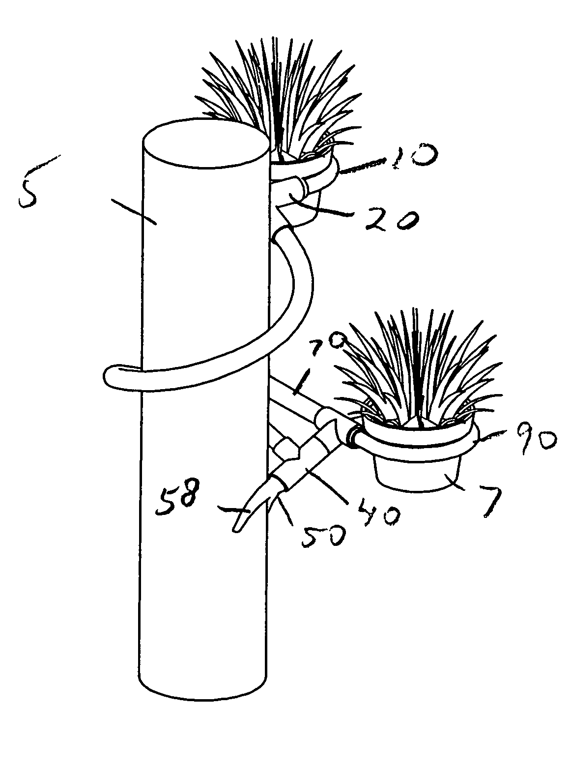
[0141]FIG. 26 shows a rear perspective view of the embodiment 1 of the preceding figures with telescoping adjustable loop holders 80 and 90. Attachment ends 82, 92 of bottom loop holders 80, 90 can be elongated to telescoping slide in and out in the direction of arrow T into the open ends of t-shaped coupler 60. Alternatively extension couplers 70 can be attached to either or both of the attachment ends 82, 92 of the bottom loop holders 80, 90.

[0142]FIG. 27 shows a front perspective view of the preceding embodiment where the loop holders 10, 80, 90 can rotate in the direction of arrow A and be reversible to opposite locations relative to the coil member by their respective attachment ends 12, 82, 92 being able to twist within their respective couplers 20, 70 and 60.

[0143]FIG. 28 shows a front perspective view of the preceding embodiment showing further adjustability by moving both the loop holders 10, 80 and 90 together with their respective couplers 20, and 60 in the direction of a...

second embodiment

[0144]FIG. 31 shows a front perspective of another embodiment 200 with two top loop holders 280 and 290 and one loop holder 210 on the bottom of the coil shaped member 30 wrapped about an underlying support member 5 that is supporting objects 7. FIG. 32 shows a front perspective view of the stand 200 of FIG. 31 without the supported objects 7 and the underlying support member 5. This embodiment can have an upper left loop holder 280 with extender coupler 270 and upper right loop holder 290 connected by an upper t-shaped coupler to an upper end of the coil member 30. The bottom of the coil member 30 can connect to another t-shaped coupler 240 that also connect a fork stabilizer and single bottom loop holder 210 with curved coupler 220. The second embodiment components can be assembled together with slip fittings similar to that of the preceding embodiment and also be similarly mounted to an underlying support member 5.

embodiment 300

[0145]FIG. 33 shows a front left perspective of another embodiment 300 of the stand without coupler connector fittings as single molded piece. FIG. 34 is a front right perspective view of the embodiment 300 of FIG. 33. The invention can be formed and molded from a single pipe member to have a generally coil shaped configuration with upper loop holder 310 and bottom left and right loop holders 380 and 390 in place.

[0146]FIG. 35 shows a front right perspective of another embodiment 400 with adjustable, extendable fork stabilizer 450 being installed into t-shaped couplers 440, 460. FIG. 36 shows the telescoping adjustability of the fork stabilizer 450 of FIG. 35 with coupler 70 having an optional side through-hole. FIG. 37 shows a side view of the fork stabilizer 450 being adjusted for a large diameter underlying support member 5A. FIG. 38 shows a side view of the fork stabilizer 450 being adjusted for a smaller diameter underlying support member with loop holders 10, 80 being adjusted...


PUM


Abstract

Coil / helix shaped stands and methods of using and installing the stands that can be wrapped about elongated supports. The stands can have looped holders for supporting objects such as planters and pots, off ground level. The looped holders can be adjustable so as to remain level with different size diameter elongated supports. The stands can be aesthetically pleasing and attractive and be easy to assembly and mount. The stands are easily removable. Additionally, the coil stands can support other objects such as tables, flagpoles and umbrellas.

Description

[0001]This invention is a continuation-in-part of U.S. Design Pat. application Ser. No. 29 / 263,713 filed Jul. 28, 2006 now U.S. Pat. No. D. 575,138.FIELD OF INVENTION[0002]This invention relates to stands and holders, in particular to stand devices, apparatus and methods for wrapping about tree trunks and tree limbs and poles and pillars and table legs and railing supports, that can be used for holding and displaying pots, planters, flowers, plants, bird seed, tables, beverages and food items and other objects off the ground.BACKGROUND AND PRIOR ART[0003]Backyards and gardens have become increasingly popular to display plants and flowers in pots and planters. Attempts have been made to display pots and plants that have included ground based stands and elevated supports. Many of these stands can require assembly time and be expensive to purchase and assemble, as well as be unsightly and unattractive. In addition, such stands take up valuable ground space which restricts use and enjoy...

Claims


Application Information

Patent Timeline
IPC IPC(8): A47B96/06
CPCA45B11/00A47G7/044
Inventor LONDO, KEVIN C.
Owner LONDO KEVIN C
Learn More