
Electrical oscillator circuit and an integrated circuit

an oscillator circuit and integrated circuit technology, applied in the field of electric and integrated circuits, can solve the problems of low power consumption sensitive arrangement of oscillators, and achieve the effects of small power consumption, low noise, and small capacity

Inactive Publication Date: 2010-03-09
TELEFON AB LM ERICSSON (PUBL)
View PDF2 Cites 1 Cited by
  • Summary
  • Abstract
  • Description
  • Claims
  • Application Information

AI Technical Summary

Benefits of technology

[0014]Consequently, the oscillating electrical signal is provided as a single-ended signal with diminished noise sensitivity. The oscillation information, provided by the resonator, in the single-ended signal can thus be extracted and used by components in the second subcircuit for obtaining very exact timing information with the use of a minimum of components.
[0022]When the CMOS type transistor is coupled with its source terminal to the ground reference of the second subcircuit, with its drain terminal to a current or voltage supply and to one of the electrical conductors and with its gate connected to the other of the electrical conductors, a single-element active device is provided. This can further reduce the power consumption.
[0024]When the means is connected to supply the single-ended signal to components comprised in the second subcircuit, a simple system for distributing a low noise oscillator signal to the components comprised in the second subcircuit is provided.
[0025]The oscillator can be powered by a capacitor. It is possible to supply the oscillator with power from a capacitor with small capacity during exchange of e. g. a battery pack. This is possible due to the small power consumption.

Problems solved by technology

Consequently, the prior art involves the problem that oscillators arranged to consume low power are sensitive to noise induced on the electrical conductors extending between the resonator and the active device.

Method used


Image

  • Electrical oscillator circuit and an integrated circuit
  • Electrical oscillator circuit and an integrated circuit
  • Electrical oscillator circuit and an integrated circuit

Examples


Embodiment Construction

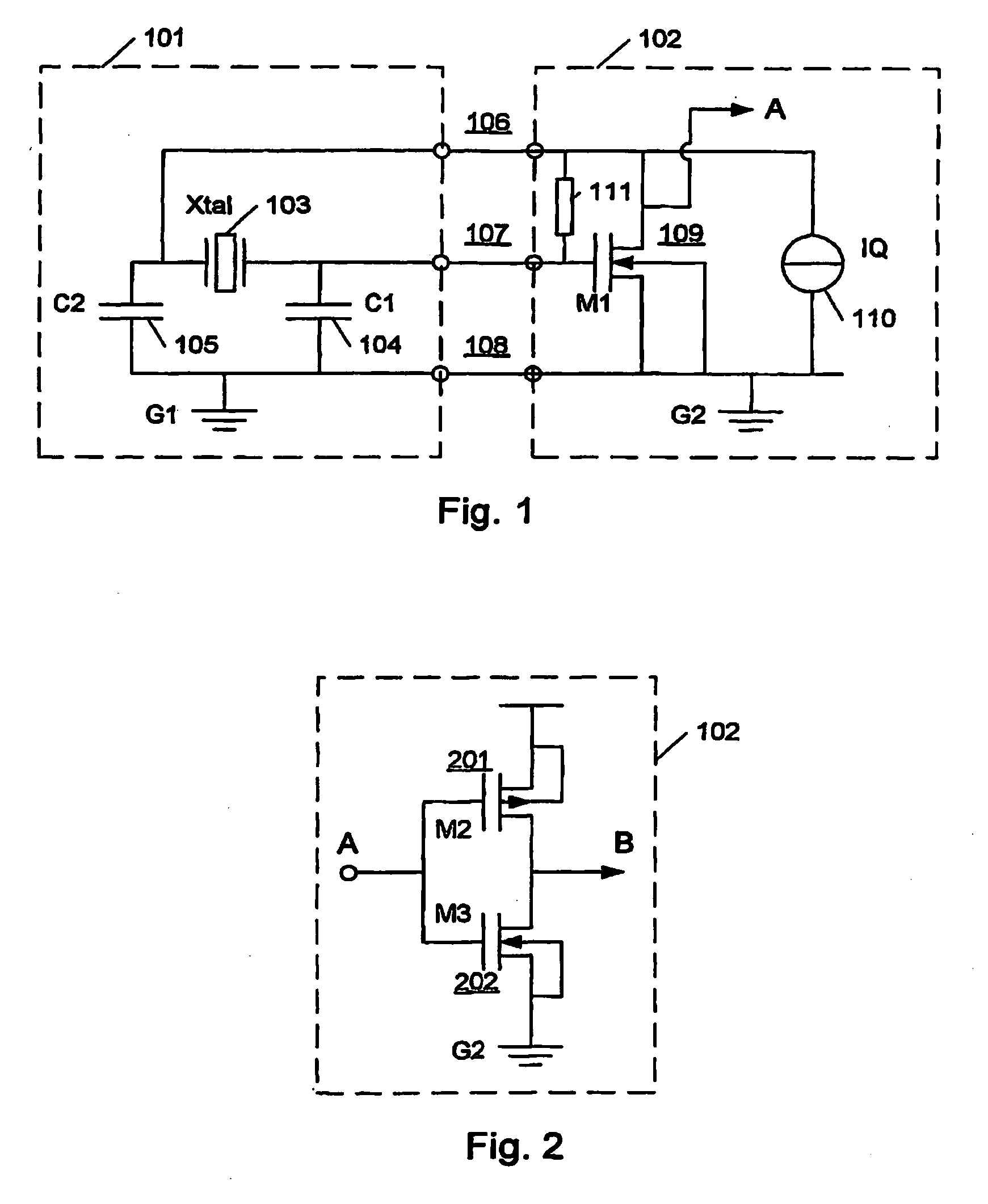
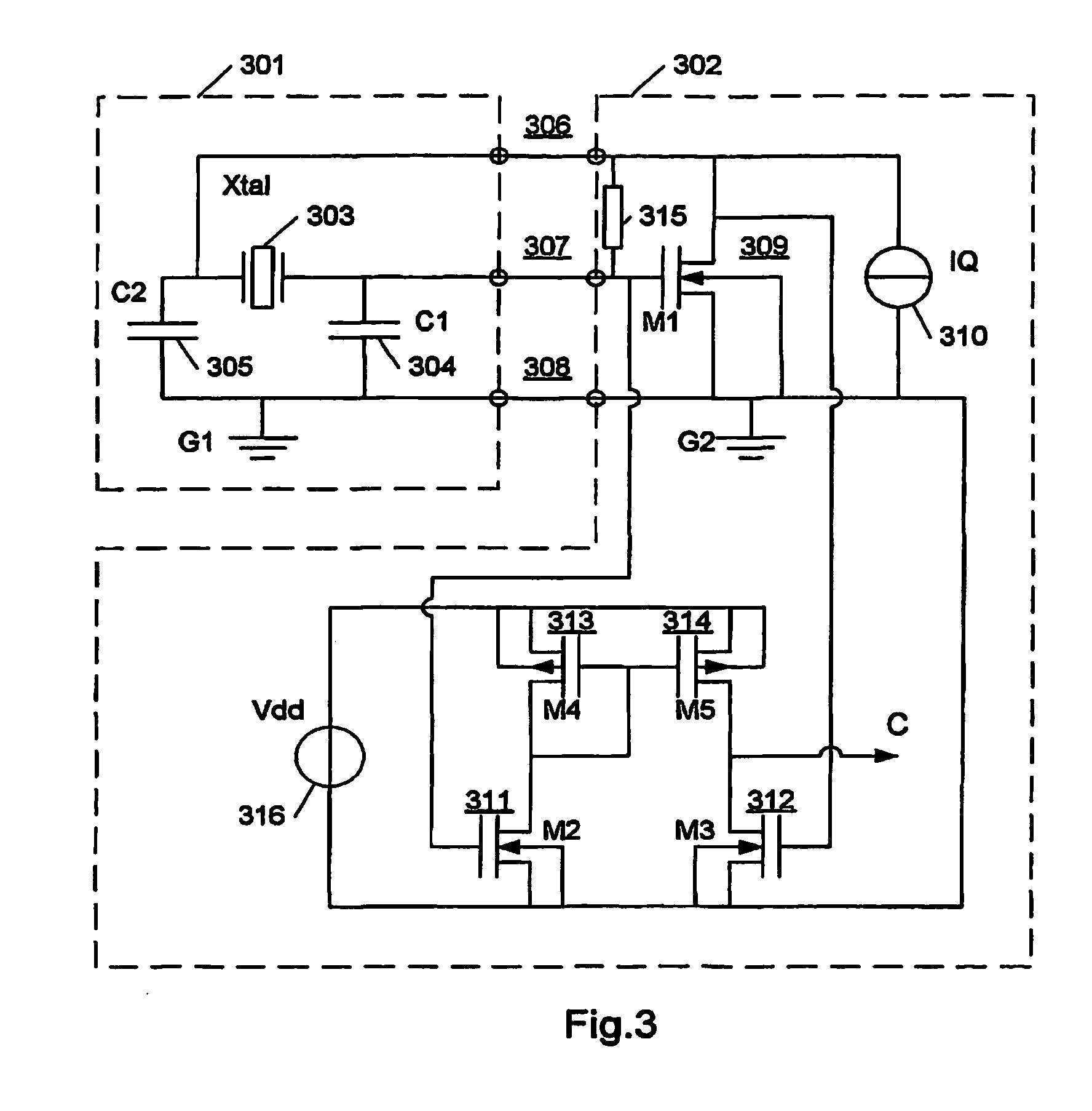
[0031]FIG. 1 shows an electrical oscillator circuit. The oscillator circuit is illustrated to comprise a first and a second subcircuit. The first subcircuit 101 is typically implemented by means of passive components mounted on a printed circuit board (PCB), whereas the second subcircuit 102 is implemented on a substrate in an integrated circuit (IC) component that is mounted on the PCB.

[0032]The first subcircuit 101 comprises an oscillating device in the form of a crystal (Xtal) 103 for instance with a nominal oscillating frequency of 32 Kilo Hertz. The crystal is electrically connected to the second subcircuit 102 by means of two connectors 106 and 107.

[0033]At frequencies about the nominal series resonance frequency the crystal has a relatively low impedance. However, at frequencies below and above the series resonance frequency the crystal has a relatively high impedance. Thus, below and especially above the nominal frequency an oscillating signal across the crystal will be sens...


PUM


Abstract

An electrical oscillator circuit comprising: a resonator comprised in the first subcircuit; and an active device comprised in the second subcircuit connected to energize the resonator to provide an oscillating electrical signal transmitted as a differential signal via electrical conductors to the second subcircuit. The oscillator is characterized in that the second subcircuit comprises means for receiving the differential signal transmitted via the electrical conductors and converting the differential signal to a single-ended signal with reference to the signal ground reference of the second subcircuit. Thereby a noise robust oscillator signal is provided with the use of very few components. Particularly suitable for oscillators embodied in an integrated circuit with the resonator mounted on a printed circuit board, PCB. And an integrated circuit.

Description

CROSS-REFERENCE TO RELATED APPLICATIONS[0001]This patent application is a continuation of U.S. patent application Ser. No. 10 / 478,973 filed on May 27, 2004 now U.S. Pat. No. 7,432,772. This application incorporates by reference the entire disclosure of U.S. patent application Ser. No. 10 / 478,973.[0002]This patent application claims the benefit of priority from U.S. Provisional Patent Application Ser. No. 60 / 298,408 filed on Jun. 18, 2001. This application incorporates by reference the entire disclosure of U.S. Provisional Patent Application Ser. No. 60 / 298,408.TECHNICAL FIELD OF THE INVENTION[0003]This invention relates to an electrical oscillator circuit comprising: a first subcircuit and a second subcircuit with a signal ground reference; a resonator unit comprised in the first subcircuit; an active device comprised in the second subcircuit connected to energize the resonator to provide an oscillating electrical signal transmitted as a differential signal via electrical conductors...

Claims


Application Information

Patent Timeline
Patent Type & Authority Patents(United States)
IPC IPC(8): H03B5/32H03B5/36
CPCH03B5/364
Inventor MATTISSON, SVEN
Owner TELEFON AB LM ERICSSON (PUBL)
Learn More